20
4.6
Start/stop/shutdown
Start of the unit
•
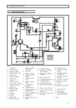
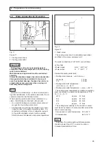
The electric motor -3- starts up in the Y-mode.
•
The intake regulator -2- is closed.
•
The oil supply of the screw compressor -4- is provid-
ed by the vacuum pressure where the injection takes
place.
•
The cooling water solenoid valve -29-
(only in W-
units)
opens as it is energized.
•
When changing over to
∆
-operation, the solenoid
valves -19 + 20- switch due to being energized.
•
The air in the system circulates via the solenoid valve
-19- into the lower pressure chamber of the actuating
cylinder -2.1-. The upper control chamber of the actu-
ating cylinder -2.1- is isolated from the pressure res-
ervoir -6- by solenoid valve -20- and is bled into the
intake channel.
•
The pressure control valve -2.2- in the intake regula-
tor -2- opens.
•
The valve combination (pressure holding and check
valve) -15- opens at a system pressure of approx.
4,5 bar.
4. Design and functioning
4.4
Oil circuit
The required oil is drawn from the pressure reservoir-6-,
passes through the oil thermostat -21- (closes the by-
pass line of the oil cooler -12- and opens the passage to
the oil cooler at an oil temperature > 55 °C), through the
oil filter -11- and is fed to the screw compressor -4-.
The oil separated in the fine separator -7- is fed through
an oil line to the screw compressor -4-. The entire oil
circulation is based on a natural differential pressure in
the system. Considering the pressure difference of ap-
prox. 1.5 bar within the oil circuit, the oil is then injected
into the compressor -4- with approx. 5.5 bar at a reservoir
pressure of e.g. 7 bar.
During idle running of the screw compressor, the re-
quired oil injection quantity is achieved owing to the fact
that a sufficiently high pressure drop occurs and thus,
with the inlet controller -2- being closed, a vacuum pres-
sure develops at the inlet connection (place of injection).
Automatic operation
(open/close operation)
• When the mains pressure reaches the maximum va-
lue set at pressure monitor -17-, the solenoid valves -
19 + 20- de-energize.
• The pressure control valve -2.2- closes. This happens
because the lower control chamber of the actuating
cylinder -2.1- is relieved by the de-energized soleno-
id valve -19- and as a result of the pressurization of
the upper control chamber in the actuating cylinder -
2.1- and the force of the compression spring in the ac-
tuating cylinder -2.1-.
• The screw compressor -4- is running in the idle mode.
• The pressure reservoir -6- is depressurized.
• If the mains pressure does not fall to the minimum va-
lue set at pressure monitor -17- or at the sensor of the
mains pressure B1 within 6 minutes, the system shuts
down.
• The cooling water solenoid valve -29- (only WS-units)
de-energizes and closes.
• If the minimum value preset at pressure monitor -17-
or at the sensor of the mains pressure B1 is reached
in less than 6 minutes, the solenoids -19 + 20- are
again energized.
• The unit changes over to load operation.
4.5
Air circuit
The intake air passes through the suction filter -1- and
the intake regulator -2- into the screw compressor -4-.
During the compression process, the intake air is coo-
led via the injected oil, and the developed air/oil mix-
ture flows tangentially into the pressure reservoir (oil
reservoir) -6-. After the pre-separation and the subse-
quent fine separation in the oil fine separator -7-, the
compressed air with a low oil content passes through
the valve combination -15-, the air cooler -16- and the
condensate separator (option) into the consumer net-
work.
The condensate separated in the condensate separa-
tor (option) is carried to the outside via a solenoid valve
(option) which is to be installed by the customer and con-
trolled by a "Kondensomat“ (option).
•
The delivery of compressed air into the consumer
network starts.
Throttling operation (option)
• The upper switching point is set to the maximum ope-
rating pressure at pressure monitor -17- or, depen-
ding on the machine version, at the sensor of the
mains pressure B1 (0.3 bar higher than the setting of
the proportional regulator). The standard proportional
regulator can only be used for a pressure range of
between 7 bar and the nominal pressure.
• The regulation range can be set lower by adjusting
the proportional regulator accordingly.
• With an increasing input pressure (increasing pressu-
re in the pressure reservoir -6-), the proportional regu-
lator provides a decreasing output pressure within the
regulating range (corresponds to a decreasing pilot
pressure in the lower control chamber of the actuator -
2.1-).
• As a result of the pressure drop in the lower control
chamber, the compression spring in the upper control
chamber partly closes the pressure control valve -2.2-
and thus causes throttling of the intake flow.
Note
The throttling operation provides only a restricted
throttling function, the task of which is to reduce the
supply flow to 70 %. When this value is reached, the
pressure monitor -17- or the mains pressure sensor B1
(depending on the machine version) switches the
screw compressor unit over to automatic operation.


