19
4.3
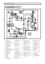
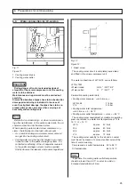
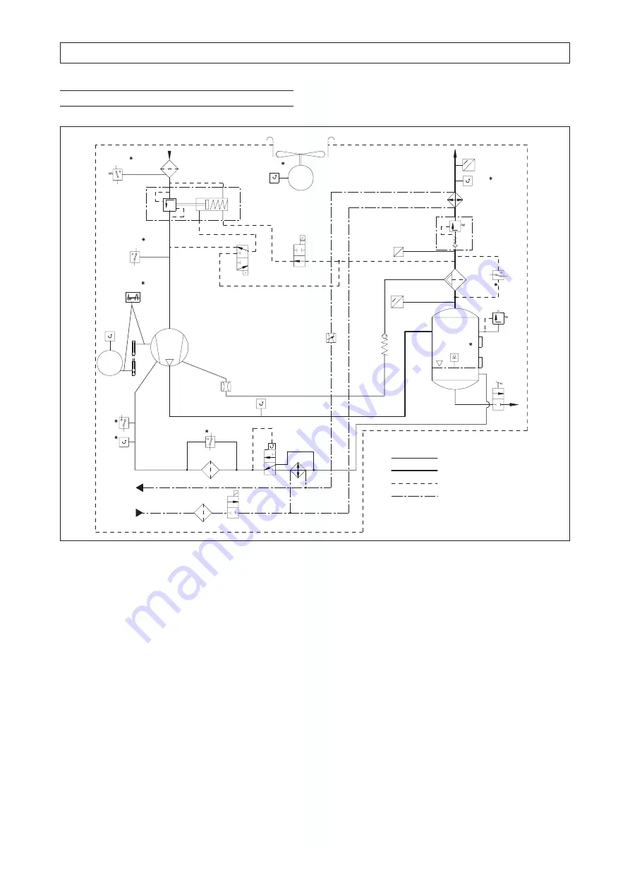
Schematic diagram
1.
Intake filter
2.
Intake regulator
2.1 Actuating cylinder
2.2 Pressure control valve
3.
Electric motor
4.
Screw compressor
5.
Thermo-
indicator
6.
Pressure reservoir
7.
Fine separator cartridge
8.
Oil drain ball valve
9.
Safety valve
10. Switch of oil filter
(maintenance)*
11. Oil filter
12. Oil cooler
13. Throttle
14. Check valve
15. Valve combination:
Fig. 5
4. Design and functioning
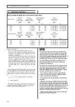
27. Dirt trap (WS only)
28. Cooling water solenoid
valve (WS only)
29. Throttle valve, settable
(WS only)
R1 Motor temperature*
R2 Compressor temperature
R3 Oil injection temp.*
R4 Ventilator motor temp.*
R6 After-cooler temperature*
B1 Sensor mains pressure*
B2 Sensor compression end
pressure
B3 Sensor outlet of the oil fine
separator*
S3 Pressure monitor
S5 Differential pressure
oil filter*
S6 Differential pressure
fine separator*
S7 Differential pressure
air filter*
S8 Oil injection pressure*
S10 Direction of rotation
monitor*
S12 Oil level*
S13 Bearing monitor SPM*
Y1 Regulating valve
Y4 Blow-off valve
Y6 Cooling water sole-
noid valve (WS only)
* option
Pressure h
check valve
16. Air cooler
17. Pressure monitor
18. Pressure m
display
19. 3/2-way solenoid
valve
20. 2/2-way solenoid
valve
21. Oil temperature
regulator
22. Oil level indicator
23. Switch of intake filter
(maintenance)*
24. Switch of fine separator
(maintenance)*
25. Ventilator
26. Clogging indicator of air
filter
1
2
3
4
5
6
7
8
9
10
11
12
13
15
16
18
19
20
21
22
23
24
25
2.1
R1
R2
R3
R4
R6
B1
B2
B3
S5
S6
S7
S8
S10
S12
S13
Y1
Y4
14
27
28
29
2.2
Y6
S3
1 )
1 )
U
P
M
M
p
-u
-i
p
-u
-i
d
c
b
a
L37-75


