Comfort Glow HFVMR18 Скачать руководство пользователя страница 6

901915-01B

For more information, visit www.desatech.com

For more information, visit www.desatech.com

6

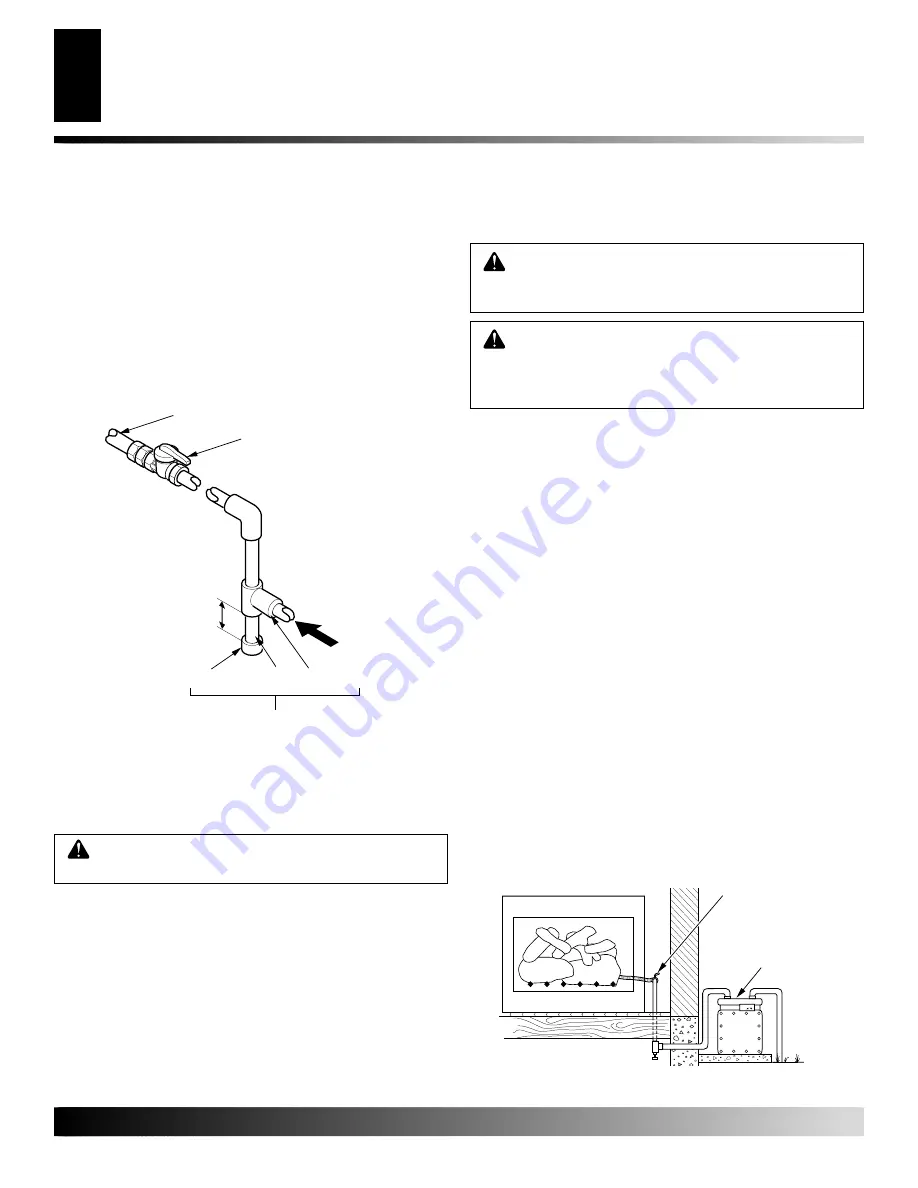
Figure 5 - Checking Gas Joints

INSTALLATION

Continued

 WARNING: Test all gas piping and connections,

internal and external to unit, for leaks after installing
or servicing. Correct all leaks at once.

 WARNING: Never use an open flame to check for

a leak. Apply a noncorrosive leak detection fluid to
all joints. Bubbles forming show a leak. Correct all
leaks at once.

CHECKING GAS CONNECTIONS

Pressure Testing Gas Supply Piping System

Test Pressures In Excess Of 1/2 PSIG (3.5 kPa)

1.

Disconnect appliance with its appliance main gas valve (control
valve) and equipment shutoff valve from gas supply piping sys-
tem. Pressures in excess of 1/2 psig will damage heater regulator.

2.

Cap off open end of gas pipe where equipment shutoff valve
was connected.

3.

Pressurize supply piping system by either using compressed air or
opening main gas valve located on or near gas meter.

4.

Check all joints of gas supply piping system. Apply noncor-
rosive leak detection fluid to gas joints. Bubbles forming show
a leak.

5.

Correct all leaks at once.

6.

Reconnect log set and equipment shutoff valve to gas supply.
Check reconnected fittings for leaks.

Test Pressures Equal To or Less Than 1/2 PSIG (3.5 kPa)

1.

Close equipment shutoff valve (see Figure 5).

2.

Pressurize supply piping system by either using compressed air or
opening main gas valve located on or near gas meter.

3.

Check all joints from gas meter to equipment shutoff valve (see
Figure 5). Apply noncorrosive leak detection fluid to gas joints.
Bubbles forming show a leak.

4.

Correct all leaks at once.

We recommend that you install a sediment trap in supply line as
shown in Figure 4. Locate sediment trap where it is within reach for
cleaning. Install in piping system between fuel supply and heater.
Locate sediment trap where trapped matter is not likely to freeze. A
sediment trap traps moisture and contaminants. This keeps them
from going into log set controls. If sediment trap is not installed or
is installed wrong, log set may not run properly.

Installation must include an equipment shutoff valve, union, and
plugged 1/8" NPT tap. Locate NPT tap within reach for test gauge
hook up. NPT tap must be upstream from log set (see Figure 4).

IMPORTANT:

 Install equipment shutoff valve in an accessible

location. The equipment shutoff valve is for turning on or shutting
off the gas to the appliance.

Apply pipe joint sealant lightly to male threads. This will prevent
excess sealant from going into pipe. Excess sealant in pipe could
result in a clogged burner injector.

 WARNING: Use pipe joint sealant that is resistant

to liquid petroleum (LP) gas.

Figure 4 - Gas Connection

* Purchase the optional CSA design-certified equipment shutoff
valve from your dealer. See Accessories, page 17.
** Minimum inlet pressure for purpose of input adjustment.

3" Minimum

Sediment Trap

From Gas Meter
(5" W.C.** to 10.5"
W.C. Pressure)

CSA Design-Certified
Equipment Shutoff Valve
With 1/8" NPT Tap*

Approved
Gas Hose

Tee Joint

Pipe Nipple

Cap

Gas Meter

Equipment Shutoff Valve

INSTALLATION

Connecting To Gas Supply (Cont)
Checking Gas Connections

Содержание HFVMR18

Страница 1: ...oradditionalinformationcon sult a qualified installer service agency or the gas supplier WARNING This appliance is for installationonlyinasolid fuelburn ing masonry or UL127 factory built fireplace co...

Страница 2: ...use any phone in your building immediately call your gas supplier from a neighbor s phone Follow the gas supplier s instructions if you cannot reach your gas supplier call the fire department 3 Never...

Страница 3: ...fts that alter burner flame patterns Ceiling fans can create drafts that alter burner flame patterns Altered burner patterns can increase sooting 9 Do not use a blower insert heat exchanger insert or...

Страница 4: ...ound windows and doors to keep the cold air out and the warm air in During heating months home owners want their homes as airtight as possible While it is good to make your home energy efficient your...

Страница 5: ...ndicated FUEL INLET PRESSURE SPECIFICATIONS W C Min Max NG 5 5 10 5 LP 11 13 Figure 2 Technical Information Charts BURNER ORIFICE LOG NATURAL PROPANE LP SIZE IN NUM IN NUM 18 111 34 073 49 24 129 30 0...

Страница 6: ...m gas meter to equipment shutoff valve see Figure 5 Apply noncorrosive leak detection fluid to gas joints Bubbles forming show a leak 4 Correct all leaks at once We recommend that you install a sedime...

Страница 7: ...nued HEARTH KIT ASSEMBLY AND INSTALLATION Kit Assembly 1 Unscrew burner inlet fitting from burner manifold 2 Place burner manifold in pan with threaded opening facing open knockout plug see Figure 6 M...

Страница 8: ...tting Off Appliance Turn gas shutoff valve clockwise to the OFF position 1 STOP Read the safety information above 2 Turn the gas shutoff valve to OFF 3 Wait five 5 minutes to clear out any gas If you...

Страница 9: ...how log set was malfunctioning type of gas used propane LP or natural gas purchase date Usually we will ask you to return the part to the factory PARTS NOT UNDER WARRANTY Contact authorized dealers of...

Страница 10: ...urner orifice size Log set is smoking sooting excessively Note It is natural and unavoidable for vented gas log sets to produce moderate levels of carbon soot where flames contact the logs This is esp...

Страница 11: ...Gas leak SeeWarning statement at top of page OBSERVED PROBLEM Log Set produces a clicking ticking noise just after burner is lit or shut off Log Set produces unwanted odors Gas odor even when control...

Страница 12: ...nformation visit www desatech com For more information visit www desatech com 12 ILLUSTRATED PARTS BREAKDOWN MODELS HFVMR18 AND HFVMR24 3 6 12 10 11 10 4 7 9 5 1 8 2 ILLUSTRATED PARTS BREAKDOWN Models...

Страница 13: ...01 901066 01 Brass Air Mixer Natural Gas 1 4 901064 10 901064 03 Natural Gas Injector 1 5 901763 02 901763 01 Burner Manifold 1 6 901767 02 901767 01 Burner Pan 1 7 901242 01 901242 01 Damper Clamp S...

Страница 14: ...instructions listed under Replacement Parts on page 9 of this manual KEY PART NUMBER FOR NO 18 24 DESCRIPTION QTY 1 901656 01 901657 01 Bottom Front 1 2 2 901666 01 901667 01 Bottom Front 2 2 3 901619...

Страница 15: ...Completed College Completed Graduate School 13 Age of Purchaser Under 20 20 29 30 39 40 49 50 59 60 or Over 14 Buyer s total annual household income Under 15 000 15 000 to 19 999 20 000 to 34 999 35...

Страница 16: ...901915 01B For more information visit www desatech com For more information visit www desatech com 16 2701 Industrial Drive P O Box 90004 Bowling Green KY 42102 9004 Postage Required TAPE TAPE...

Страница 17: ...emote control operation Contains components for propane LP conversion INDIVIDUAL ROUND LOG GA9450A Not Shown Fordecorativepurposesonly Nottobeusedasadditionallogsonunit INDIVIDUAL SPLIT LOG GA9550A No...

Страница 18: ...ic cost labor transportation and any and all such other costs related to repairing a defective log set will be the responsibility of the owner TO THE FULL EXTENT ALLOWED BY THE LAW OF THE JURISDICTION...

Отзывы: