Tech Support: 1‐818‐841‐5500
5
Cabling and control depends on how the user desires to control the AF10‐CE. Use the above table
to determine which cable to use. If the AF10‐CE is paired with an AutoFill unit, refer to the AutoFill
manual for additional wiring information.
Blast Control:
Pin 1 provides 115VAC power from the AccuFlo. The host must provide a switch to
put this voltage back in to Pin 2, which will cause the blaster to blast. When Pin 2 is left floating,
the blaster will not blast. 200mA of current is typical.
PE:
Pin 4 provides an optional bonding path to Primary Earth through the AccuFlo. If the host is
otherwise bonded to PE, do not use this pin.
Regulator Control:
The regulator must be powered by 24vdc through Pin 7 and ground through Pin
6. The regulator requires 60mA of current. The blast pressure is set by providing a 0‐10vdc signal
at Pin 8, which corresponds to a pressure of 0‐148psi. The internal resistance of the regulator’s
input is 100ohms minimum.
AF10‐CE Cables and Controllers
A10‐CE Control Connector
Содержание AccuFlo AF10-CE
Страница 1: ...Comco Inc 2151 N Lincoln St Burbank CA 91504 USA Tech comcoinc com 1 818 841 5500 ...
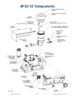
Страница 8: ...AF10 CE Components 1 818 841 5500 8 www comcoinc com ...
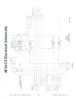
Страница 11: ...Tech Support 1 818 841 5500 11 tech comcoinc com AF10 CE Electrical Schematic Rev 12 7 21 ...
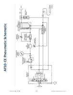
Страница 12: ...AF10 CE Pneumatic Schematic 1 818 841 5500 12 www comcoinc com ...


