


Modular Optical Switch
|
SwitchBlade
Coherent Solutions
|
SwitchBlade
(V1.4)
9
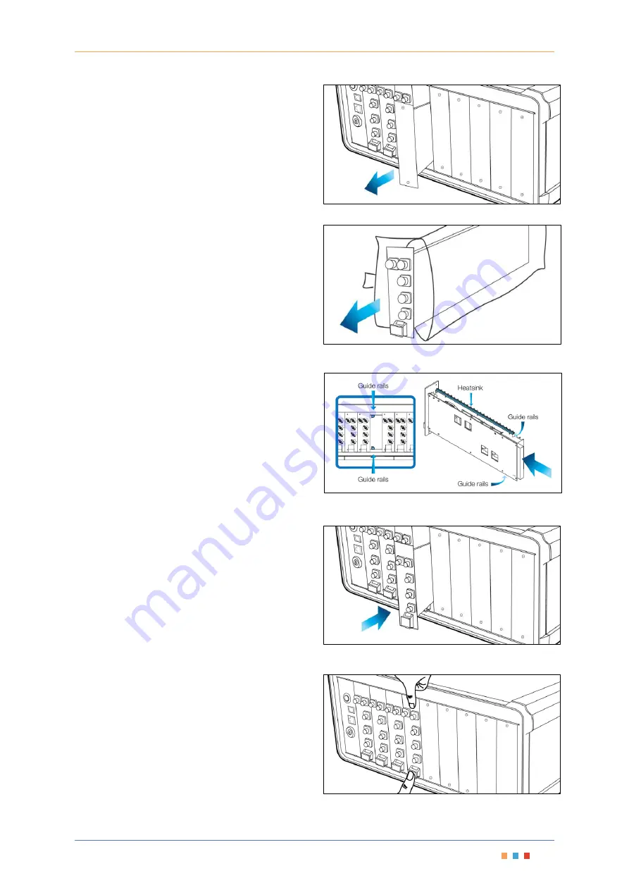
3.
Slide the
blanking module
out to remove it and
store the
blanking module
near the
MTP1000 for future use.
Figure 6 - Remove Blanking Module
Remove the SwitchBlade from packaging
4.
Unpack the SwitchBlade module from the
antistatic packaging, making sure to store the
packaging near the MTP1000 so it is available to
safely store any SwitchBlade that may be
removed in the future.
Figure 7 - Remove and store Antistatic Packaging
Insert the SwitchBlade securing into place
5.
Slide the SwitchBlade into the available slot using
the guide rails.
6.
Once the SwitchBlade reaches the connector at
the end of the slot, press your thumbs on the
release latch
and the top of the SwitchBlade
module as shown in Figure 10
to make sure the
SwitchBlade seats correctly.
Figure 9 - Install the SwitchBlade Module
Figure 10 - Press the SwitchBlade Module to seat it into the
Connector
Figure 8 - MTP1000 and SwitchBlade Guide Rails
Содержание SwitchBlade
Страница 1: ......
Страница 40: ...V1 4...


