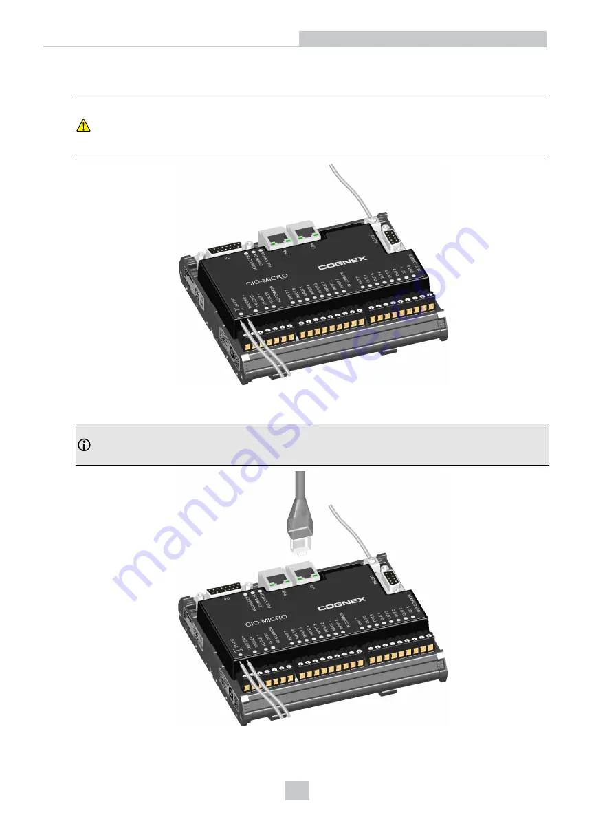
5. Connect a frame ground wire to the I/O module’s Frame Ground terminal. Connect the other end of the frame
ground wire to frame ground.
CAUTION
:
The shield ground connections of the RS-232 port, LAN port, PoE port, I/O port and Frame
Ground terminal are internally connected. The system grounding is at a zero ground potential. This zero-
ground potential extends through the cable and to peripheral equipment, such as a vision system or PLC.
To ensure safe operating conditions, check ground connections to ensure that they meet a zero ground
potential.
6. To connect the vision system to an Ethernet network, plug a LAN cable (RJ-45 connector) into the I/O module’s
LAN port and connect the other end of the cable to a switch/router or PC, as applicable.
Note
: The CIO-MICRO I/O module does not support 1000 BaseT pass-through operation. If 1000 BaseT
operation is required, you must connect an RJ-45 LAN cable from a Gigabit PoE switch to the I/O module’s
LAN port and connect the vision system’s Ethernet cable to the Gigabit PoE switch.
17
Installation


