background image

23

9. Mounting the Module / Finishing the Installation

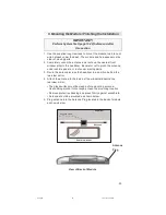
Rear-View Mirror

Antenna

Headliner

Antenna Cable

IMPORTANT!

Perform System Test (page 19-22) before and after

this section.

1. Use the supplied long tie wraps to mount the module to a brace or

wire harness under the dash. The module and harnesses must be
clear of moving parts.

2. Completely uncoil the antenna and route up the nearest front

window pillar to the headliner. Be careful not to pinch the antenna
under vehicle panels, or route near moving parts.

3. Route the antenna across the headliner to a position behind the

rearview mirror.

4. Attach the antenna to the inside of the windshield behind the

rearview mirror:

• The glass surface must be clean before mounting antenna.

Use rubbing alcohol to thoroughly clean the mounting location.

• Remove protective backing and press firmly against windshield.

• Antenna should be mounted as shown below.

5. Plug antenna into the Antenna Plug located in the back of module

as shown below.

View of Back of Module

Antenna

Plug

630.p65

10/17/03, 7:29 PM

23

Содержание CA-630

Страница 1: ...void locking keys in vehicle during installation FCC COMPLIANCE This device complies with Part 15 of the FCC rules and with RSS 210 of Industry Canada Operation is subject to the following two conditions 1 This device may not cause harmful interference and 2 This device must accept any interference received including any interference that may cause undesired operation Warning Changes or modificati...

Страница 2: ...sed 16 Horn SirenOutput BLACK 17 Disarm OverrideButton Ground PLUGIN 18 Disarm OverrideButtonInput PLUGIN 19 HoodPinInput GRAY 20 DoorTriggerInput GRN VT 21 FactoryAlarmDisarm BRN BLK 22 LED2 Red PLUGIN 23 LED1 Black PLUGIN 24 SecondDoorUnlock 500ma BLU GRN System Layout System Layout CA 630TM A Advanced Harness B Basic Harness C Car Start Harness Note The wire connection sections will identify ea...

Страница 3: ...l module to positive or negative 2 B Lock Motor Wire 16 AWG BLUE 1 A Lock Switch Wire 87A 16 AWG BLUE BLACK 14 B Unlock Motor Wire 16 AWG GREEN 3 A Unlock Switch Wire 87A 16AWG GREEN BLACK 24 B Second Door Unlock 16 AWG BLUE GREEN IMPORTANT After installation set the polarity of this circuit by moving the fuse inside of the control module to positive or negative Type 1 Positive 3 wire door lock sy...

Страница 4: ...cle s unlock wire as shown in Diagram 4 below Connect wires 14 B 3 A as shown in Diagram 2 above 1 Basic Harness B cont d Cut From driver s Door Unlock Relay only To driver s Door Motor only 3 A Unlock Switch 14 B Unlock Motor Diagram 2 Wires from control module Unlock Motor 14 B Unlock Switch 3 A Lock Motor 2 B Lock Switch 1 A Vehicle Master Switch To Door Lock Motors Diagram 3 24 B Fused 12v Fro...

Страница 5: ...Connect the 24 B wire to the vehicle unlock wire Use a SPDT relay not supplied and refer to Diagram 5 to connect to the vehicle s driver s unlock wire Type 4 Vacuum Door Lock System Polarity Fuse Positive Note Two stage unlock will not work with this type of system 1 Basic Harness B cont d Cut Here From Driver s Door Only Unlock Switch or Relay Fused 12v Diagram 5 To Driver s DoorUnlock Motor 14 B...

Страница 6: ...inside of the control module to positive or negative polarity Single Stage Unlock Two Stage Unlock Connect the 2 B wire as shown in Diagram 7 above Connect the 24 B wire as shown in Diagram 8 below Connect the 14 B wire as shown in Diagram 9 below 1 Basic Harness B cont d Diagram 7 14 B Ground for positive polarity system 12v fused for negative polarity system 12v fused Cut Diagram 9 From Switch S...

Страница 7: ... Door Lock Motors Diagram 3 Type 1 POS Type 3 NEG 3 wire door lock system Second stage unlock Connect the 2 B wire to the vehicle lock wire Connect the 13 B wire to the vehicle unlock wire Select Polartiy with Fuse Location Type 2 Door Lock Systems Type 2 Reverse Polarity Door Lock Systems 630 p65 10 17 03 7 29 PM 7 ...

Страница 8: ...not ground the 5B wire with any other vehicle components 6 B Starter Input Key Side 14 AWG VIOLET RED 8 B Starter Output Motor Side 14 AWG VIOLET Locate the vehicle starter wire Verification This wire registers voltage only when the key is turned to the START position Cut the vehicle starter wire in half Verification after starter wire is cut KEY SIDE of starter wire registers voltage when the key...

Страница 9: ...IMPORTANT After installation set the polarity of this circuit by moving the fuse inside of the control module to positive or negative 17 B 18 B Emergency Override Button 20 AWG Find a mounting location for the override button that is not easily seen or openly accessible There must be at least 1 clearance behind the location Dr i l la9 32 hole and mount the button 19 B Hood Safety 20 AWG GRAY Insta...

Страница 10: ...E SYSTEMS TEMPORARILY CONNECT THE 20 B WIRE TO GROUND IN ORDER TO ACCESS THE PROGRAMMING MODE CHANGE OPTION BANK 4 FEATURE 1 TO POSITIVE POLARITY PAGE 20 16 B Horn Relay Drive 500mA 18 AWG BLACK Locate the vehicle horn wire Verification This wire will register either positive or ground when the horn is pressed Connect the 16 B wire to the vehicle horn wire if the system is negative If the system i...

Страница 11: ...ssary to cut that wire and connect 9 A to the switch side of that wire Note See 13 B description Basic Harness 11 A Rear Defrost Output Aux 2 500ma 20 AWG BLU WHITE Locate the vehicle rear window defrost wire Verification This wire will register either positive voltage or ground when the rear defroster is turned on Connect the 11 A wire to the vehicle defrost wire if the system is negative If the ...

Страница 12: ... wire registers voltage when the key is turned to the ON or RUN position but not the ACC Accessory position The voltage drops when the key is turned to the START or CRANK position Connect 2 C to a main power wire at the ignition switch preferably to a wire other than the 4 B main power connection 5 C HVAC 2 Output 14 AWG ORANGE WHITE 1 C HVAC 2 Polarity Input 14 AWG BLUE Note Use these wires if th...

Страница 13: ...k or neutral and no voltage in all other positions 9 C Tach Input VIOLET WHITE Connect the 9 C wire to wire at negative side of the vehicle ignition coil or fuel injector Verification Refer to Vehicle Wire Color and Location Chart for the wire color and location or test using the following procedure 1 Set voltmeter to AC VOLTS 2 Attach positive lead of meter to a constant 12 volt source 3 Attach n...

Страница 14: ...e than one relay install 1 amp blocking diodes 1N4001 or equivalent as shown in the Diagram 14 Interrupting a Sensor or Component while the Vehicle is running via Remote Start Use an SPDT relay not supplied and connect as shown in Diagram 15 3 Car Start Harness C cont d 10 C WIRE ToAlarm FromSensor Constant12V Cut Here SensorTriggerWire Diagram 15 InstallDiodesHere Diodestripeshould face toward mo...

Страница 15: ...ram two transmitters three 3 times and the remaining transmitter twice 1 Open the driver s door 1 a The 20 B wire must initially see a ground to access programming 2 Turn vehicle ignition on 3 Press and hold emergency override button After 10 seconds the siren or horn will sound three 3 times This indicates that the unit has entered the transmitter programming mode 4 Release the button 5 Press the...

Страница 16: ...cator on the dashboard indicates whether an option is on or off If the selected option is ON the indicator will light If the selected option is OFF the indicator will turn off The status indicator will turn on or off when an option is changed 5 When changes are complete press and release the emergency override button to continue to the next option bank Siren or horn will sound five 5 times 6 To re...

Страница 17: ... a normal idle 5 10 seconds The unit will chirp the Siren Horn and flash the parking lights every three 3 seconds to indicate that it has learned the current idle speed 4 System Power Up and Programming cont d Afjustable Crank TimeTable 1 1 A d j u s t a b l e C r a n k T a b l e o f C h i r p s D u r a t i o n 1 0 7 4 S e c 2 0 8 7 S e c 3 1 0 S e c 4 1 1 S e c 5 1 2 S e c 6 1 4 S e c 7 1 5 S e c...

Страница 18: ...al ON 1 OFF 2 6 Horn Siren 1 Horn 2 Siren ON 1 OFF 2 7 Noise Control Alarmwill 1 soundforfive30 sec cycles ON 1 OFF 2 thenignoretriggeror 2 Soundcontinuously whentriggeredifanentranceisleftopen 8 HornOutput 1 RealPanic 2 PulsedOutput ON 1 OFF 2 Option Bank Three 6 Chirps Car Start Options 1 TachMode 1 Use blind crank timing 2 Usetachinput ON 1 OFF 2 2 BlindCrankTime 1 Avgoflast8manualstarts 2 1sec...

Страница 19: ...ks to see if brake is pressed If so parking lights flash two 2 times and vehicle will not start If the above conditions are not present 1 Parking lights flash once 2 Factory alarm if equipped is turned off 3 Factory VATS or PATS systems if equipped are interfaced active output is activated 4 Interior Sensor is disabled 5 Vehicle ignition turns on 6 Heater AC are powered 7 Vehicle starter begins to...

Страница 20: ...is enabled the starter will crank for 1 of 7 pre selected times The unit will assume that the vehicle has started You must select the time desired for each specific vehicle refer to pg 20 for the time table Note In Blind Crank Timing or Adjustable Crank modes over rev protection is disabled if selected Press and hold START while vehicle is running via remote start 1 Vehicle shuts off 2 Parking lig...

Страница 21: ...m if equipped is turned off 3 Courtesy lights turn on for 60 seconds or until LOCK is pressed or ignition is turned on Press UNLOCK twice 1 If Silent Choice Verification is set horn sounds once 2 Passenger doors unlock if using 2 stage unlock Press FIND PANIC Siren horn sounds 5 times Press and hold FIND PANIC for 1 second Horn sounds and lights flash for 30 seconds or until any remote control but...

Страница 22: ...nected to another device the device will activate Press and hold UNLOCK Trunk or hatch opens or other device activates AS LONG AS BUTTON IS HELD If Ignition Lock option is set to On Doors lock when all doors are closed and key is turned to ON position If Ignition Unlock option is set to On Doors unlock when ignition is turned off If Illuminated Exit option is set to On Dome will turn on once ignit...

Страница 23: ...er Be careful not to pinch the antenna under vehicle panels or route near moving parts 3 Route the antenna across the headliner to a position behind the rearview mirror 4 Attach the antenna to the inside of the windshield behind the rearview mirror The glass surface must be clean before mounting antenna Use rubbing alcohol to thoroughly clean the mounting location Remove protective backing and pre...

Страница 24: ...24 630 p65 10 17 03 7 29 PM 24 ...

Отзывы: