background image

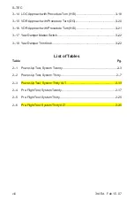
Содержание S-TEC Thirty

Страница 1: ......

Страница 2: ...hanged added or deleted by current revision Record of Revisions Retain this record in front of handbook Upon receipt of a revision insert changes and complete table below Revision Number Revision Date...

Страница 3: ...ii 3rd Ed Feb 15 07 S TEC Page Intentionally Blank...

Страница 4: ...1 4 2 Pre Flight Procedures 2 1 2 1 Power Up Test 2 3 2 1 1 System Twenty 2 3 2 1 2 System Thirty 2 7 2 1 3 System ThirtyALT 2 13 2 2 Pre Flight Test 2 17 2 2 1 SystemTwenty 2 17 2 2 2 SystemThirty 2...

Страница 5: ...s SystemThirty ThirtyALT 3 8 3 1 6 1 System Thirty 3 8 3 1 6 2 System ThirtyALT 3 8 3 2 Approach Procedures 3 11 3 2 1 Straight In LOCApproach 3 11 3 2 1 1 Heading System DG 3 11 3 2 1 2 Heading Syste...

Страница 6: ...22 3 3 1 AUTO Mode 3 22 3 3 2 ON Mode 3 22 3 3 3 Yaw Damper Trim 3 22 3 4 Autopilot Disconnect 3 23 3 4 1 System Twenty Thirty 3 23 3 4 2 System ThirtyALT 3 23 4 Operating Parameters 4 1 4 1 RollAxis...

Страница 7: ...2 8 2 8 AP Display ALT Lamp Only Illuminated System Thirty 2 9 2 9 AP Display All Lamps Extinguished System Thirty 2 9 2 10 AP Display RDY for Operation System Thirty 2 10 2 11 AP Display Turn Coordi...

Страница 8: ...ty ALT 2 36 2 29 ALT HOLD ON OFF Switch Display ALT HOLD Mode Engaged TRIM UP Required System ThirtyALT 2 36 2 30 ALT HOLD ON OFF Switch Display ALT HOLD Mode Engaged TRIM DN Required System ThirtyALT...

Страница 9: ...ocedure Turn HSI 3 21 3 17 Yaw Damper Master Switch 3 22 3 18 Yaw Damper Trim Knob 3 22 List of Tables Table Pg 2 1 Power Up Test System Twenty 2 3 2 2 Power Up Test System Thirty 2 7 2 3 Power Up Tes...

Страница 10: ...3rd Ed Feb 15 07 1 1 S TEC SECTION 1 OVERVIEW...

Страница 11: ...1 2 3rd Ed Feb 15 07 S TEC Page Intentionally Blank...

Страница 12: ...irectly proportional to the pilot s knowledge of its operating procedures Therefore it is highly recommended that the pilot develop a thorough understanding of the autopilot its modes and operating pr...

Страница 13: ...k HI TRK Mode Used to Track a LOC Course Note A heading system HSI or DG is optional If the aircraft is equipped with a heading system then the heading mode can be engaged Otherwise the heading mode c...

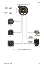
Страница 14: ...3rd Ed Feb 15 07 1 5 S TEC Fig 1 1 System Twenty Block Diagram...

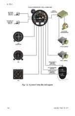
Страница 15: ...1 6 3rd Ed Feb 15 07 S TEC Fig 1 2 System Thirty Block Diagram...

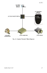
Страница 16: ...3rd Ed Feb 15 07 1 7 S TEC Fig 1 3 System Thirty ALT Block Diagram...

Страница 17: ...1 8 3rd Ed Feb 15 07 S TEC Fig 1 4 Yaw Damper Block Diagram...

Страница 18: ...3rd Ed Feb 15 07 2 1 S TEC SECTION 2 PRE FLIGHT PROCEDURES...

Страница 19: ...2 2 3rd Ed Feb 15 07 S TEC Page Intentionally Blank...

Страница 20: ...ON position 4 Set Autopilot Master Switch to ON position RDY ST HD LO TRK and HI TRK lamps illuminate on AP display as shown in Fig 2 1 for 7 seconds and then extinguish as shown in Fig 2 2 RDY lamp...

Страница 21: ...2 4 3rd Ed Feb 15 07 S TEC Fig 2 1 AP Display RDY ST HD LO TRK HI TRK Lamps Illuminated at Power Up System Twenty Fig 2 2 AP Display All Lamps Extinguished System Twenty...

Страница 22: ...3rd Ed Feb 15 07 2 5 S TEC Fig 2 3 AP Display RDY for Operation System Twenty Fig 2 4 AP Display Turn Coordinator Failure System Twenty...

Страница 23: ...2 6 3rd Ed Feb 15 07 S TEC Fig 2 5 AP Display Low Voltage Flag System Twenty...

Страница 24: ...RIM DN lamps illuminate on AP display as shown in Fig 2 6 TRIM UP lamp extinguishes after 2 seconds as shown in Fig 2 7 RDY ST HD LO TRK HI TRK and TRIM DN lamps extinguish after 7 seconds as shown in...

Страница 25: ...2 8 3rd Ed Feb 15 07 S TEC Fig 2 6 APDisplay RDY ALT ST HD LO TRK HI TRK TRIM UP TRIM DN Lamps Illuminated at Power Up System Thirty Fig 2 7 AP Display TRIM UP Lamp Extinguished System Thirty...

Страница 26: ...3rd Ed Feb 15 07 2 9 S TEC Fig 2 9 AP Display All Lamps Extinguished System Thirty Fig 2 8 AP Display ALT Lamp Only Illuminated System Thirty...

Страница 27: ...2 10 3rd Ed Feb 15 07 S TEC Fig 2 11 AP Display Turn Coordinator Failure System Thirty Fig 2 10 AP Display RDY for Operation System Thirty...

Страница 28: ...3rd Ed Feb 15 07 2 11 S TEC Fig 2 12 AP Display Low Voltage Flag System Thirty...

Страница 29: ...2 12 3rd Ed Feb 15 07 S TEC Page Intentionally Blank...

Страница 30: ...er Switch to OFF position if installed 2 Set Battery Master Switch to ON position 3 Set Avionics Master Switch to ON position 4 Set ALT HOLD Master Switch to ON position ALT ON UP and DN lamps illumin...

Страница 31: ...3rd Ed Feb 15 07 S TEC Fig 2 13 ALT HOLD ON OFF Switch Display ALT ON UP and DN Lamps Illuminated at Power Up System Thirty ALT Fig 2 14 ALT HOLD ON OFF Switch Display UPLamp Extinguished System Thirt...

Страница 32: ...3rd Ed Feb 15 07 2 15 S TEC Fig 2 15 ALT HOLD ON OFF Switch Display DN Lamp Extinguished System Thirty ALT Fig 2 16 ALT HOLD ON OFF Switch Display ALT ON Lamp Extinguished System Thirty ALT...

Страница 33: ...2 16 3rd Ed Feb 15 07 S TEC Page Intentionally Blank...

Страница 34: ...R Turn Knob to the left side of its index A C Control Wheel turns to the left 6 Turn L R Turn Knob to the right side of its index A C Control Wheel turns to the right 7 Set L R Turn Knob under its in...

Страница 35: ...to select a local VOR frequency on Navigation Receiver then proceed to step 26 Otherwise proceed to step 13 13 Select local VOR frequency on Navigation Receiver Note Proceed to either step 14 HSI or s...

Страница 36: ...3rd Ed Feb 15 07 2 19 S TEC Fig 2 17 AP Display ST Mode Engaged System Twenty Fig 2 18 AP Display HD Mode Engaged System Twenty...

Страница 37: ...k mode HI TRK lamp alone is illuminated on AP display as shown in Fig 2 20 23 Turn OBS until CDI needle deflection is 2 dots right of center A C Control Wheel turns to the right 24 Turn OBS until CDI...

Страница 38: ...3rd Ed Feb 15 07 2 21 S TEC Fig 2 19 AP Display LO TRK Mode Engaged System Twenty Fig 2 20 AP Display HI TRK Mode Engaged System Twenty...

Страница 39: ...Control Wheel left and right A C Control Wheel s increased freedom of movement indicates that Roll Servo is disengaged Note If a Yaw Damper is installed then proceed to step 30 Otherwise proceed to s...

Страница 40: ...er Pedal slowly moves forward 36 Turn Yaw Trim Knob CCW until A C Rudder Pedals stop 37 Set Yaw Damper Master Switch to OFF position 38 Actuate A C Rudder Pedals alternately in succession A C Rudder P...

Страница 41: ...2 24 3rd Ed Feb 15 07 S TEC Page Intentionally Blank...

Страница 42: ...e 5 Turn L R Turn Knob to the left side of its index A C Control Wheel turns to the left 6 Turn L R Turn Knob to the right side of its index A C Control Wheel turns to the right 7 Set L R Turn Knob un...

Страница 43: ...to select a local VOR frequency on Navigation Receiver then proceed to step 26 Otherwise proceed to step 13 13 Select local VOR frequency on Navigation Receiver Note Proceed to either step 14 HSI or s...

Страница 44: ...3rd Ed Feb 15 07 2 27 S TEC Fig 2 21 AP Display ST Mode Engaged System Thirty Fig 2 22 AP Display HD Mode Engaged System Thirty...

Страница 45: ...k mode HI TRK lamp alone is illuminated on AP display as shown in Fig 2 24 23 Turn OBS until CDI needle deflection is 2 dots right of center A C Control Wheel turns to the right 24 Turn OBS until CDI...

Страница 46: ...3rd Ed Feb 15 07 2 29 S TEC Fig 2 23 AP Display LO TRK Mode Engaged System Thirty Fig 2 24 AP Display HI TRK Mode Engaged System Thirty...

Страница 47: ...d do not use 31 Move A C Control Wheel as far forward as possible After 3 seconds TRIM UP lamp becomes illuminated on AP display as shown in Fig 2 26 and audible alert sounds a steady tone After 7 sec...

Страница 48: ...3rd Ed Feb 15 07 2 31 S TEC Fig 2 25 AP Display HI TRK and ALT HOLD Modes Engaged System Thirty...

Страница 49: ...2 32 3rd Ed Feb 15 07 S TEC Fig 2 26 AP Display HI TRK andALT HOLD Modes Engaged TRIM UPRequired System Thirty Fig 2 27 APDisplay HI TRK andALT HOLD Modes Engaged TRIM DN Required System Thirty...

Страница 50: ...s illuminated and audible alert is squelched 36 Move A C Control Wheel left and right A C Control Wheel s increased freedom of movement indicates that Roll Servo is disengaged 37 Move A C Control Whee...

Страница 51: ...se 42 Turn Yaw Trim Knob fully CCW Left A C Rudder Pedal slowly moves forward 43 Turn Yaw Trim Knob fully CW Right A C Rudder Pedal slowly moves forward 44 Turn Yaw Trim Knob CCW until A C Rudder Peda...

Страница 52: ...rol Wheel s reduced freedom of movement indicates that Pitch Servo is engaged Pitch Servo can be overridden If not disconnect autopilot and do not use 4 Move A C Control Wheel as far forward as possib...

Страница 53: ...F Switch Display ALT HOLD Mode Engaged System Thirty ALT Fig 2 29 ALT HOLD ON OFF Switch Display ALT HOLD Mode Engaged TRIM UP Required System Thirty ALT Fig 2 30 ALT HOLD ON OFF Switch Display ALT HO...

Страница 54: ...A C Rudder Pedals alternately in succession to sense their freedom of movement about yaw axis 11 Set Yaw Damper Master Switch to ON position 12 Turn Yaw Trim Knob until A C Rudder Pedals stop 13 Atte...

Страница 55: ...ls stop 17 Set Yaw Damper Master Switch to OFF position 18 Actuate A C Rudder Pedals alternately in succession A C Rudder Pedals increased freedom of movement indicates that Yaw Servo is disengaged 19...

Страница 56: ...3rd Ed Feb 15 07 3 1 S TEC SECTION 3 IN FLIGHT PROCEDURES...

Страница 57: ...3 2 3rd Ed Feb 15 07 S TEC Page Intentionally Blank...

Страница 58: ...he ST lamp alone will be illuminated as shown in Fig 3 1 to acknowledge that this mode is engaged The autopilot will hold the aircraft at wings level Turning the L R Turn Knob to the left or right of...

Страница 59: ...e desired heading on the compass card HSI or DG and then engage the heading mode The HD lamp alone will be illuminated as shown in Fig 3 2 to acknowledge that this mode is engaged The autopilot will t...

Страница 60: ...heading of the selected course Engage the low track mode The LO TRK lamp alone will be illuminated as shown in Fig 3 3 to acknowledge that this mode is engaged The autopilot will track the selected co...

Страница 61: ...ver the aircraft to within 1 CDI needle width and 10 heading of each successive course segment Engage the high track mode The HI TRK lamp alone will be illuminated as shown in Fig 3 4 to acknowledge t...

Страница 62: ...de ST HD LO TRK HI TRK is already engaged Maneuver the aircraft to the desired altitude Engage the altitude hold mode The ALT lamp will be illuminated as shown in Fig 3 5 to acknowledge that this mode...

Страница 63: ...audible alert will sound a steady tone If no action is taken after four more seconds then the lamp will flash and the audible alert will become periodic Once the aircraft has been sufficiently trimmed...

Страница 64: ...3rd Ed Feb 15 07 3 9 S TEC Fig 3 7 AP Display Manual Trim Prompts System Thirty a TRIM UP Required b TRIM DN Required...

Страница 65: ...3 10 3rd Ed Feb 15 07 S TEC a TRIM UP Required b TRIM DN Required Fig 3 8 ALT HOLD ON OFF Switch Display Manual Trim Prompts System Thirty ALT...

Страница 66: ...The autopilot will track the FRONT INBOUND LOC course A summary pictorial of this procedure is shown in Fig 3 10 3 2 2 Straight In VOR Approach 3 2 2 1 Heading System DG Select the VOR frequency on th...

Страница 67: ...Turn Heading Bug to establish aircraft on FRONT INBOUND LOC course e Engage high track mode f Track FRONT INBOUND LOC course 2 a At middle marker if missed approach is declared disconnect autopilot b...

Страница 68: ...heading d Engage heading mode e Turn Heading Bug to establish aircraft on FRONT INBOUND LOC course f Engage high track mode g Track FRONT INBOUND LOC course 2 a At middle marker if missed approach is...

Страница 69: ...gage heading mode e Turn Heading Bug to establish aircraft on FRONT INBOUND VOR course f Engage high track mode g Track FRONT INBOUND VOR course 2 a At middle marker if missed approach is declared dis...

Страница 70: ...d Engage heading mode e Turn Heading Bug to establish aircraft on FRONT INBOUND VOR course f Engage high track mode g Track FRONT INBOUND VOR course 2 a At middle marker if missed approach is declare...

Страница 71: ...l track the FRONT INBOUND LOC course A summary pictorial of this procedure is shown in Fig 3 13 3 2 3 2 Heading System HSI Select the LOC frequency on the Navigation Receiver For reference only set th...

Страница 72: ...Heading Bug to FRONT OUTBOUND PROCEDURE TURN heading 3 a Turn Heading Bug in two successive 90 increments to establish aircraft on FRONT INBOUND PROCEDURE TURN heading 4 a Turn Heading Bug to establi...

Страница 73: ...FRONT OUTBOUND LOC course 2 a Set Heading Bug to FRONT OUTBOUND PROCEDURE TURN heading 3 a Turn Heading Bug in two successive 90 increments to establish aircraft on FRONT INBOUND PROCEDURE TURN headin...

Страница 74: ...igh track mode The autopilot will track the FRONT INBOUND VOR course A summary pictorial of this procedure is shown in Fig 3 15 3 2 4 2 Heading System HSI Select the VOR frequency on the Navigation Re...

Страница 75: ...VOR course 2 a Set Heading Bug to FRONT OUTBOUND PROCEDURE TURN heading 3 a Turn Heading Bug in two successive 90 increments to establish aircraft on FRONT INBOUND PROCEDURE TURN heading 4 a Turn Hea...

Страница 76: ...TBOUND VOR course 2 a Set Heading Bug to FRONT OUTBOUND PROCEDURE TURN heading 3 a Turn Heading Bug in two successive 90 increments to establish aircraft on FRONT INBOUND PROCEDURE TURN heading 4 a Tu...

Страница 77: ...ervo is engaged Fig 3 17 Yaw Damper Master Switch ON AUTO OFF TRIM YAW DAMPER Fig 3 18 Yaw Trim Knob 3 3 1 AUTO Mode With the Yaw Damper Master Switch in the AUTO position the yaw servo will become au...

Страница 78: ...on Control Wheel for 3 seconds 3 Press Hold PUSH MODE Switch located on bezel for 3 seconds 4 Set Autopilot Master Switch to OFF position 5 Pull Autopilot Circuit Breaker 3 4 2 System Thirty ALT The a...

Страница 79: ...3 24 3rd Ed Feb 15 07 S TEC Page Intentionally Blank...

Страница 80: ...3rd Ed Feb 15 07 4 1 S TEC SECTION 4 OPERATING PARAMETERS...

Страница 81: ...4 2 3rd Ed Feb 15 07 S TEC Page Intentionally Blank...

Страница 82: ...90 Standard Rate Turn Turboprop A C 75 Standard Rate Turn 4 2 Pitch Axis Limits Altitude 32 000 FT Vertical Force Due to Acceleration 0 60 g Modes For the System Thirty the pitch mode ALT HOLD can on...

Страница 83: ...4 4 3rd Ed Feb 15 07 S TEC Page Intentionally Blank...

Страница 84: ...3rd Ed Feb 15 07 5 1 S TEC SECTION 5 GLOSSARY...

Страница 85: ...5 2 3rd Ed Feb 15 07 S TEC Page Intentionally Blank...

Страница 86: ...e FAA Federal Aviation Administration FT Feet GPS Global Positioning System HD Heading HI TRK High Track HSI Horizontal Situation Indicator IFR Instrument Flight Rules LO TRK Low Track LOC Localizer M...

Страница 87: ...5 4 3rd Ed Feb 15 07 S TEC Page Intentionally Blank...

Страница 88: ...n contained in this document is subject to change without notice 2007 S TEC All rights reserved Printed in the United States of America S TEC and the S TEC logo are registered trademarks of S TEC Noti...

Отзывы: