570-2000, Rev. E, 453-2000 Handheld Programmer Operations Manual
6.
Programming Verification
Artex requires that a verification test as described in the following subsections be
performed. All testing should be done inside some type of metal enclosure that will
attenuate any radio frequency emissions. It is possible for the 406 MHz transmission to
reach an SAR satellite if the signal is not attenuated or shielded.
6.1
ELT Testing Precautions
CAUTION:
PERFORM ALL ELT TESTING IN ACCORDANCE WITH LOCAL OR NATIONAL
REGULATIONS. IF REQUIRED, TERMINATE ELT INTO A 50-OHM LOAD OR PERFORM
TESTING IN AN RF SHIELDED ENVIRONMENT.
ELTS WITH 121.5/243 MHZ TRANSMITTERS MUST BE TESTED WITHIN 5 MINUTES
AFTER THE HOUR (US/CANADA). LIVE TRANSMISSIONS OF THE 406 MHZ SIGNAL
MUST BE LIMITED TO ELTS THAT TRANSMIT A “SELF-TEST” USING TEST FRAME
SYNCHRONIZATION. EXTENDED TESTING OF THE 406 MHZ ELT SIGNAL MUST BE
PERFORMED DIRECTLY CONNECTED TO THE PROGRAMMER WITH PROPER SIGNAL
ATTENUATION AND/OR RF SHIELDING. SEE “OPTIONAL EQUIPMENT”.
6.2
ELT Reader Function (Sarcalc)
The ELT Reader function of the Handheld Programmer uses a separate software
program called “Sarcalc”. This software must be opened and run separately from the
Artex Programming software. The Sarcalc program (sarcalc.prc, version 2.33 or higher)
is pre-installed on the Meazura
unit in ROM memory. In the event the program is lost
or needs to be re-installed, it may be installed using the Palm Desktop
application and
the Meazura
serial or USB cable.
NOTE
: The ELT read function does not detect or verify the presence of 121.5 MHz; this
is a 406 MHz reader only.
1.
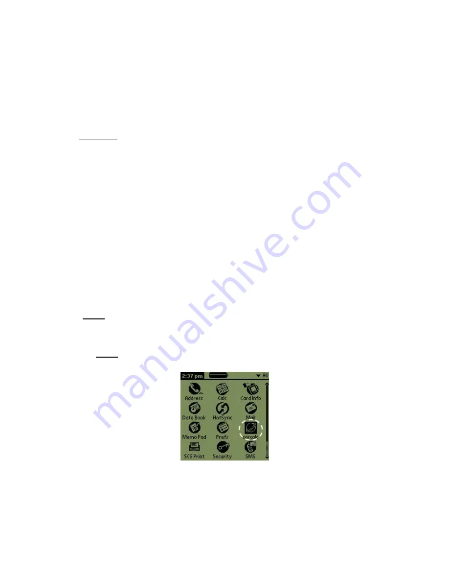
Select the Sarcalc program by tapping the “Sarcalc” icon (Figure 13).
NOTE
: The exact location of the Sarcalc icon may vary depending on what other
programs or applications are loaded on the Handheld Programmer.
Figure 13: Sarcalc Icon
2.
Connect the reader to the ELT directly with a coax cable (no attenuator required for
test set) or connect the whip antenna.
The reader is now ready to receive and decode the message.
3.
Select “Measure” from “Avionic Tools” screen, as shown in Figure 14.
Page 25


