


Page 34
VM1350-1500-1600 Operating Manual
WARNING
Make sure that proper grinding discs are always being used,
otherwise the machine or the valve body can be damaged:
If grinding discs are used for lapping operation, they will be
damaged!
If already used lapping discs are utilised for grinding operation,
the required accuracy cannot be guaranteed and the valve seat
might be damaged
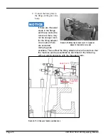
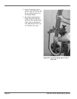
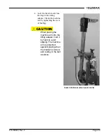
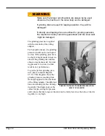
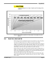
The grinding pressure is applied
with the star knob of the tilting
adapter.
For best performance, the grinding
pressure should not be too high or
too low. If the grinding pressure is
too high, it might result in heat cre-
ation at the grinding disc and the
abrasive might shear off. If grind-
ing pressure is too low, it could
result in low performance.
To get the perfect grinding pres-
sure, please consider diagram
4.5.0.2. This diagram shows the
grinding pressure resulting from
the torque applied to the star knob
of the tilting adapter. The different
lines are standing for the submerg-
ing depth. The diagram gives the
values for pre-setting the pressure
and it shows that the torque at the star knob is fairly low since the ratio of the tilt-
ing table is very high.
F
IGURE
4-1. A
PPLIANCE OF GRINDING PRESSURE AT STAR
KNOB OF TILTING ADAPTER
Содержание VM1350
Страница 2: ......
Страница 4: ...Page B VM1350 1500 1600 Operating Manual CLIMAX GLOBAL LOCATIONS ...
Страница 5: ...P N 89800 Rev 2 Page C CE DOCUMENTATION ...
Страница 12: ...Page vi VM1350 1500 1600 Operating Manual This page intentionally left blank ...
Страница 18: ...Page 6 VM1350 1500 1600 Operating Manual This page intentionally left blank ...
Страница 44: ...Page 32 VM1350 1500 1600 Operating Manual This page intentionally left blank ...
Страница 58: ...Page 46 VM1350 1500 1600 Operating Manual This page intentionally left blank ...
Страница 62: ...Page 50 VM1350 1500 1600 Operating Manual FIGURE A 1 GATE VALVE GRINDING AND LAPPING MACHINE ...
Страница 63: ...P N 89800 Rev 2 Page 51 ...
Страница 64: ...Page 52 VM1350 1500 1600 Operating Manual ...
Страница 65: ...P N 89800 Rev 2 Page 53 FIGURE A 2 440 10S N01 00 BASIC MACHINE ...
Страница 66: ...Page 54 VM1350 1500 1600 Operating Manual ...
Страница 67: ...P N 89800 Rev 2 Page 55 FIGURE A 3 240 11S N01 00 ELECTRIC DRIVE ...
Страница 68: ...Page 56 VM1350 1500 1600 Operating Manual FIGURE A 4 240 13S N01 00 PNEUMATIC DRIVE ...
Страница 69: ...P N 89800 Rev 2 Page 57 FIGURE A 5 240 15S N01 00 ELECTRIC DRIVE 115 V ...
Страница 70: ...Page 58 VM1350 1500 1600 Operating Manual FIGURE A 6 440 20S N01 00 UPPER GEAR ...
Страница 71: ...P N 89800 Rev 2 Page 59 FIGURE A 7 440 21S N01 00 UPPER GEAR ADDITIONAL PARTS FOR T 1000 ...
Страница 72: ...Page 60 VM1350 1500 1600 Operating Manual FIGURE A 8 440 32S N01 00 MACHINE ARM WITH SUBMERGING DEPTH T 600 ...
Страница 73: ...P N 89800 Rev 2 Page 61 FIGURE A 9 440 33S N01 00 MACHINE ARM WITH SUBMERGING DEPTH T 800 ...
Страница 74: ...Page 62 VM1350 1500 1600 Operating Manual FIGURE A 10 440 34S N01 00 SWING CHECK SPINDLE EXTENSION 100 ...
Страница 75: ...P N 89800 Rev 2 Page 63 FIGURE A 11 440 35S N01 00 MACHINE ARM WITH SUBMERGING DEPTH T 1000 ...
Страница 76: ...Page 64 VM1350 1500 1600 Operating Manual FIGURE A 12 440 36S N01 00 SWING CHECK SPINDLE EXTENSION 150 ...
Страница 77: ...P N 89800 Rev 2 Page 65 FIGURE A 13 440 37S N01 00 MACHINE ARM GENERAL PARTS ...
Страница 78: ...Page 66 VM1350 1500 1600 Operating Manual FIGURE A 14 440 40S N01 00 BALL JOINT ...
Страница 79: ...P N 89800 Rev 2 Page 67 FIGURE A 15 440 41S N01 00 BALL JOINT TYPE 10 ...
Страница 80: ...Page 68 VM1350 1500 1600 Operating Manual FIGURE A 16 170 30S N01 00 ...
Страница 81: ...P N 89800 Rev 2 Page 69 FIGURE A 17 440 42S N01 00 BALL JOINT TYPE 15 ...
Страница 82: ...Page 70 VM1350 1500 1600 Operating Manual FIGURE A 18 170 10S N01 00 ...
Страница 83: ...P N 89800 Rev 2 Page 71 FIGURE A 19 MOUNTING SYSTEM ...
Страница 84: ...Page 72 VM1350 1500 1600 Operating Manual FIGURE A 20 440 51S N01 00 TILTING ADAPTER ...
Страница 85: ...P N 89800 Rev 2 Page 73 FIGURE A 21 440 52S N01 00 MOUNTING FOR VALVE BODIES WITH FLANGES ...
Страница 86: ...Page 74 VM1350 1500 1600 Operating Manual ...
Страница 87: ...P N 89800 Rev 2 Page 75 FIGURE A 22 440 53S N01 00 MOUNTING FOR VALVE BODIES WITHOUT FLANGES ...
Страница 88: ...Page 76 VM1350 1500 1600 Operating Manual FIGURE A 23 440 55S N01 00 SWING CHECK ADAPTER ...
Страница 89: ...P N 89800 Rev 2 Page 77 FIGURE A 24 440 57S N01 00 TILTING ADAPTER ADDITIONAL PARTS FOR T 1000 ...
Страница 90: ...Page 78 VM1350 1500 1600 Operating Manual Tooling ...
Страница 91: ...P N 89800 Rev 2 Page 79 ...
Страница 92: ...Page 80 VM1350 1500 1600 Operating Manual FIGURE A 25 240 71S N01 00 PLANET WHEELS DN 80 DN 350 ...
Страница 93: ...P N 89800 Rev 2 Page 81 FIGURE A 26 240 73S N01 00 PLANET WHEELS DN 400 DN 500 VM 1500 1600 ONLY ...
Страница 94: ...Page 82 VM1350 1500 1600 Operating Manual FIGURE A 27 110 20S N01 02 PLANET ARMS ...
Страница 95: ...P N 89800 Rev 2 Page 83 FIGURE A 28 440 72S N01 00 SOLID GRINDING DISCS DN 40 DN 65 VM 1350 ONLY ...
Страница 96: ...Page 84 VM1350 1500 1600 Operating Manual This page intentionally left blank ...
Страница 97: ......
Страница 98: ......