


Page 4
VM1350-1500-1600 Operating Manual
1.5
R
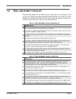
ISK ASSESSMENT AND HAZARD MITIGATION
Machine Tools are specifically designed to perform precise material-removal oper-
ations.
Stationary Machine Tools include lathes and milling machines and are typically
found in a machine shop. They are mounted in a fixed location during operation
and are considered to be a complete, self-contained machine. Stationary Machine
Tools achieve the rigidity needed to accomplish material-removal operations from
the structure that is an integral part of the machine tool.
In contrast, Portable Machine Tools are designed for on-site machining applica-
tions. They typically attach directly to the workpiece itself, or to an adjacent struc-
ture, and achieve their rigidity from the structure to which it is attached. The
design intent is that the Portable Machine Tool and the structure to which it is
attached become one complete machine during the material-removal process.
To achieve the intended results and to promote safety, the operator must under-
stand and follow the design intent, set-up, and operation practices that are unique
to Portable Machine Tools.
The operator must perform an overall review and on-site risk assessment of the
intended application. Due to the unique nature of portable machining applications,
identifying one or more hazards that must be addressed is typical.
When performing the on-site risk assessment, it is important to consider the Porta-
ble Machine Tool and the workpiece as a whole.
Содержание VM1350
Страница 2: ......
Страница 4: ...Page B VM1350 1500 1600 Operating Manual CLIMAX GLOBAL LOCATIONS ...
Страница 5: ...P N 89800 Rev 2 Page C CE DOCUMENTATION ...
Страница 12: ...Page vi VM1350 1500 1600 Operating Manual This page intentionally left blank ...
Страница 18: ...Page 6 VM1350 1500 1600 Operating Manual This page intentionally left blank ...
Страница 44: ...Page 32 VM1350 1500 1600 Operating Manual This page intentionally left blank ...
Страница 58: ...Page 46 VM1350 1500 1600 Operating Manual This page intentionally left blank ...
Страница 62: ...Page 50 VM1350 1500 1600 Operating Manual FIGURE A 1 GATE VALVE GRINDING AND LAPPING MACHINE ...
Страница 63: ...P N 89800 Rev 2 Page 51 ...
Страница 64: ...Page 52 VM1350 1500 1600 Operating Manual ...
Страница 65: ...P N 89800 Rev 2 Page 53 FIGURE A 2 440 10S N01 00 BASIC MACHINE ...
Страница 66: ...Page 54 VM1350 1500 1600 Operating Manual ...
Страница 67: ...P N 89800 Rev 2 Page 55 FIGURE A 3 240 11S N01 00 ELECTRIC DRIVE ...
Страница 68: ...Page 56 VM1350 1500 1600 Operating Manual FIGURE A 4 240 13S N01 00 PNEUMATIC DRIVE ...
Страница 69: ...P N 89800 Rev 2 Page 57 FIGURE A 5 240 15S N01 00 ELECTRIC DRIVE 115 V ...
Страница 70: ...Page 58 VM1350 1500 1600 Operating Manual FIGURE A 6 440 20S N01 00 UPPER GEAR ...
Страница 71: ...P N 89800 Rev 2 Page 59 FIGURE A 7 440 21S N01 00 UPPER GEAR ADDITIONAL PARTS FOR T 1000 ...
Страница 72: ...Page 60 VM1350 1500 1600 Operating Manual FIGURE A 8 440 32S N01 00 MACHINE ARM WITH SUBMERGING DEPTH T 600 ...
Страница 73: ...P N 89800 Rev 2 Page 61 FIGURE A 9 440 33S N01 00 MACHINE ARM WITH SUBMERGING DEPTH T 800 ...
Страница 74: ...Page 62 VM1350 1500 1600 Operating Manual FIGURE A 10 440 34S N01 00 SWING CHECK SPINDLE EXTENSION 100 ...
Страница 75: ...P N 89800 Rev 2 Page 63 FIGURE A 11 440 35S N01 00 MACHINE ARM WITH SUBMERGING DEPTH T 1000 ...
Страница 76: ...Page 64 VM1350 1500 1600 Operating Manual FIGURE A 12 440 36S N01 00 SWING CHECK SPINDLE EXTENSION 150 ...
Страница 77: ...P N 89800 Rev 2 Page 65 FIGURE A 13 440 37S N01 00 MACHINE ARM GENERAL PARTS ...
Страница 78: ...Page 66 VM1350 1500 1600 Operating Manual FIGURE A 14 440 40S N01 00 BALL JOINT ...
Страница 79: ...P N 89800 Rev 2 Page 67 FIGURE A 15 440 41S N01 00 BALL JOINT TYPE 10 ...
Страница 80: ...Page 68 VM1350 1500 1600 Operating Manual FIGURE A 16 170 30S N01 00 ...
Страница 81: ...P N 89800 Rev 2 Page 69 FIGURE A 17 440 42S N01 00 BALL JOINT TYPE 15 ...
Страница 82: ...Page 70 VM1350 1500 1600 Operating Manual FIGURE A 18 170 10S N01 00 ...
Страница 83: ...P N 89800 Rev 2 Page 71 FIGURE A 19 MOUNTING SYSTEM ...
Страница 84: ...Page 72 VM1350 1500 1600 Operating Manual FIGURE A 20 440 51S N01 00 TILTING ADAPTER ...
Страница 85: ...P N 89800 Rev 2 Page 73 FIGURE A 21 440 52S N01 00 MOUNTING FOR VALVE BODIES WITH FLANGES ...
Страница 86: ...Page 74 VM1350 1500 1600 Operating Manual ...
Страница 87: ...P N 89800 Rev 2 Page 75 FIGURE A 22 440 53S N01 00 MOUNTING FOR VALVE BODIES WITHOUT FLANGES ...
Страница 88: ...Page 76 VM1350 1500 1600 Operating Manual FIGURE A 23 440 55S N01 00 SWING CHECK ADAPTER ...
Страница 89: ...P N 89800 Rev 2 Page 77 FIGURE A 24 440 57S N01 00 TILTING ADAPTER ADDITIONAL PARTS FOR T 1000 ...
Страница 90: ...Page 78 VM1350 1500 1600 Operating Manual Tooling ...
Страница 91: ...P N 89800 Rev 2 Page 79 ...
Страница 92: ...Page 80 VM1350 1500 1600 Operating Manual FIGURE A 25 240 71S N01 00 PLANET WHEELS DN 80 DN 350 ...
Страница 93: ...P N 89800 Rev 2 Page 81 FIGURE A 26 240 73S N01 00 PLANET WHEELS DN 400 DN 500 VM 1500 1600 ONLY ...
Страница 94: ...Page 82 VM1350 1500 1600 Operating Manual FIGURE A 27 110 20S N01 02 PLANET ARMS ...
Страница 95: ...P N 89800 Rev 2 Page 83 FIGURE A 28 440 72S N01 00 SOLID GRINDING DISCS DN 40 DN 65 VM 1350 ONLY ...
Страница 96: ...Page 84 VM1350 1500 1600 Operating Manual This page intentionally left blank ...
Страница 97: ......
Страница 98: ......