10
P1799E 07/04
7STH..
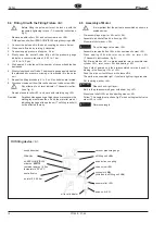
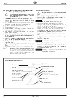
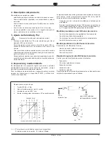
vacuum pressure gauge
oil filling unit
<A1>
quick action coupling
valve screw <88>
connector
<A2>
(includes in oil filling unit
<A>
)
needle roller <92>
pulse unit <63>
Oil filling device
<A>
sound absorber
Ultra-Vac
oil: ESSO-UNIVIS J26
order no.
925715
container approx. 150ml
temperature 20°±5°C
shut-off valve
air inlet 4,5-5,5 bar
oil level indicator
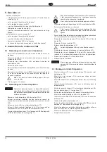
6.4 Filling Oil with the Filling Fixture <A>
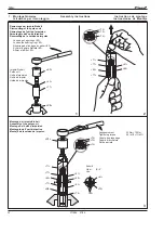
Before filling the pulse unit must be lock up with the
requested tightening torque (7. Assembly instructions,
fig. 3)
-
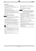
Remove needle roller <92> and valve screw asm. <88>.
-
Fill the pulse unit with oil ESSO UNIVIS J25 using the syringe
<B>
.
1. Connect the pulse unit to the quick coupling as shown below.
2. Close shut-off valve by turning it clockwise.
3. Connect supply pressure of approx. 5 bar.
4. Slowly open the shut-off valve fully until the pressure gauge
indicates a vacuum pressure of -0.95 to -1 bar.
(-13.8 to -14.5 psi).
5. Wait approx. 2 minutes until the number of vacuum bubbles has
decreased.
6. Slowly close the shut-off valve. The pressure gauge again indicates
the atmospheric pressure, missing oil is pressed into the pulse
unit.
7. Repeat the filling procedure 4. to 6. until no bubbles are formed.
8. Disconnect pulse unit from filler unit and mount valve screw <88>.
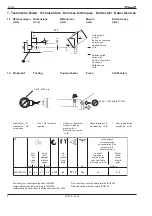
Pay attention to oil level indicator (7. Assembly instruc-
tions, fig. 4).
-
Remount needle roller <92> and save with retaining ring <93>.
Remarks:
Small bubbles appearing at high vacuum pressure in the
wetting layer between the oil and the material are not
indicating leakage of the pulse unit. The filling result will
not be affected thereby.
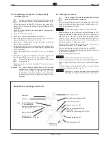
6.5 Assembly of Motor
It is important that the parts are assembled as shown in
exploded view.
-
Pre-assemble gear parts <48> until <58>.
-
Assemble air shut-off parts in housing <33>.
-
Mount distributor asm. <38>.
Caution!
Caution!
Do not damage valve stem <34>.
-
Assemble reverse button <24> with countersunk screw <23>.
-
Press bearing <39> with rotor cover <40> on rotor <43>
(7. Assembly instructions, fig. 5)
-
Put 5 times blades <42> in pre-assembled rotor, assemble rotor
cylinder <41>, rotor cover <44> and bearing <45>.
-
Take hold of geared end the pre-assembled rotor and push it
binding in the housing <15> or <33>.
-
Push the drive unit until touch with sleeve
<D>
.
-
The parts are assembled right, if you feel a light springy pressure.
-
Put in spring washer <46>.
Caution!
Caution!
Please check right layer!
-
Built in the pre-assembled gear with shear key <47>.
-
Mount seal shaft <59> and supporting sleeve <60>.
-
Follow "7. Assembly instructions, fig. 6" when setting lenth of valve
stem <25> or <34>.
Caution!
Caution!
Determine length
Содержание 7STH Series
Страница 29: ......


