background image

P1643E   04/06

9

140/160PH

5. What to Do If...

...the torque is too low?

- Is the throttle exhaust adjusted correctly?
- Is the flow pressure too low?
- Is the reverse button not in one of its end positions?
- Is the inlet screen dirty?
- Is the muffler dirty?
- Is sufficient oil in the pulse unit?

6. Repair Instructions

6.1 Motor Disassembly

-

Clamp the tool in a vice with plastic jaws on its pistol grip <1>.

Caution!

Caution!

Do not damage the rubber coating of the grip.

-

Loosen housing <62>/<89> by turning counterclockwise using a
strap wrench.

-

Pull off housing and pulse unit.

-

Remove countersunk screw <13> and reverse button <12>.

-

Knock pistol grip housing on soft surface and take power unit parts
out.

6.2 Trigger Valve Disassembly

-

Lift the plastic trigger button <22> out with 2 screwdrivers.

-

Loose the plug <21> with pin wrench 

<F>

 (pitch 11 mm, diameter

2 mm) counterclockwise.

-

Pull the loosened valve unit vertically down and out.

-

Take pieces completely out.

6.3 Motor Assembly

Caution!

Caution!

To prevent damage to the sealing and O-rings, grease
them prior to assembly with grease (Order No. 914392).


Be sure to assemble the parts in the sequence shown on
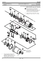
the spare parts drawing.

-

Install the O-ring <23> and the air distributor <24>.

-

To be able to push the pin into the bore on the pistol grip housing,
the radial auxiliary bore of the air distributor must be aligned with
the centre of the switch-over groove.

-

Press the roller bearing <25> together with the rotor cover <26>
onto the rotor <30> using 

<D>

 (8. Assembly Instructions, figs. 8 + 9).

Then install it in the pistol grip housing.

-

Assemble reverse button <12> and suspension bail <13>.

-

Insert rotor cylinder <28> with shear keys <27> into pistol grip
housing.

-

Insert the blades <29> into the rotor grooves.

-

Put the ball bearing <32> and the circlip <33> into the rotor cover
<31> and mount all into the pistol grip housing.

-

Assemble sleeve <34>.

Caution!

Caution!

When installing the screen <6>/<9>, be sure the circlip
<7>/<10> is lying flat on the screen.

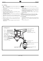
6.4 Pulse Unit Disassembly


Allowed only if filling with oil filling unit 

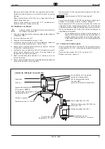
<A>

 can be

guaranteed. The pulse unit must have cooled down to
room temperature.

Caution!

Caution!

Be sure retaining rings are not extended excessively

-

With quick-disconnect attachment first remove <95> - <91>.

-

Remove retaining ring <35>/ <90>. Pull pulse unit <36>/<63> out
of


housing <62> / <89>.

-

Clamp the hydraulic cylinder  <44>/<71> slightly in a vice with flat
chops (8. Assembly Instructions, fig. 1).


To avoid endangering health or the environment, study
and comply with all Federal, State and Local Regulations.


Avoid direct skin contact when working with oil to prevent
skin irritations.

-

Remove set bolt <58>/<85>. Remove ball <57>/<84> by turning
the drive shaft <51>/<78>, keeping the opening away from the
body.

-

Loosen the bearing ring <55>/<82> with the device 

<C>

.

-

Remove the bearing ring above an oil pan and pull the hydraulic
rotor <51>/<78> from the housing.


Hydraulic roller is spring-loaded!

-

Clean all parts

Caution!

Caution!

Always only use original spares from CLECO. Use of
foreign spares entitles the manufacturer of the tool to void
the warranty.

6.5 Assembly of the Pulse Unit

Caution!

Caution!

To avoid damage to the o-rings apply grease (part
n° 914392) to them before mounting.

-

Reassemble by reversing the disassemby process as shown
(7. Spare parts exploded view).

-

Push parts <43> - <38> (   1/2") or <70> to <65> (  7/16" ) onto
the hydraulic cylinder <44>/<71> and secure them with the circlip
<37>/<64>

-

Assemble o-ring <53>/<80> and support ring <54>/<81> on
hydraulic rotor <51>/<78>.

-

Push fixture 

<E>

 over long side of shaft on hydraulic rotor

(8. Assembly instructions, fig. 2).

-

Insert compression springs and blades over the slots of fixture 

<E>

by pressing them down and turning the hydraulic rotor into the
hydraulic rotor slots (fig. 3).

-

Adjust control blade <50>/<77> (with long shaft end) towards bore
in fixture (fig. 4).

-

Assemble needle roller <45>/<72> into hydraulic cylinder.

-

Insert the preassembled parts by means of 

<E>

 into hydraulic

cylinder <44>/<71> so that needle roll <45>/<72> and bore met.
Remove 

<E>

 (fig. 5-6).

-

Mount disc <52>/<79> and positon over needle roll.

Caution!

Caution!

The control slides at the facing surface of the disk points
towards the slots in the rotor

-

Put up bearing ring <55>/<82> with o-ring <56>/<83>.

-

Clamp the pulse unit slightly in a vice with flat chops.

-

Tighten bearing ring by means of fixture 

<C>

 until the limit stop.

-

Undo the bearing ring by about 360° +90° and carry out the oil
filling:

Содержание 140PH

Страница 1: ...etter Parts Manual P1643E 2006 04 P H Max Kapazit t Rated Capacity Abtrieb Final drive 140 140 Nm Q Schnellwechself Quick change 7 16 160 160 Nm 6 Vierkant Square 3 4 Ausf hrung Style B P Pistolengrif...

Страница 2: ...l utilisateur doivent tre obligatoirement respect es par toute personne charg e de l installation le fonctionnement et la maintenance de l outil S curit Lire d abord attentivement les consignes de s...

Страница 3: ...haber le do y comprendido estas instrucciones y el manual espec fico de este modelo S mbolos Atenci n Este s mbolo indica un situaci n potencial de peligro Pueden producirse lesiones f sicas a las pe...

Страница 4: ...e r f e d i v n o i t a t o r o t o u v a t i c o l e v o c a v n e d a d i c o l e v n e s l u P e s l u p r e s l u p i s l u p m i o s l u p x a m n i m x a m n i m m m g k n i m 3 m Q 5 4 H P 0 4...

Страница 5: ...spektionsarbeiten immer Sicherheitshinweise P1687S und die typspezifische Betriebsanleitung beachten und ver wenden Nachfolgende Inspektions und Wartungsliste enth lt Zeit Kontroll und Wartungshinweis...

Страница 6: ...hnt werden Bei Schnellwechselfutter Ausf hrung zuerst 95 91 entfer nen Sprengring 35 90 demontieren Impulseinheit 36 63 aus dem Geh use 62 89 ziehen Hydr Zylinder 44 71 an Schl sselfl chen in glatten...

Страница 7: ...ung C auf das geforderte Drehmoment anziehen 8 Montagehinweise Bild 7 Kugellager 60 87 mit Sicherungsring 59 86 in Geh use 62 89 einbauen O Ring 61 88 einlegen Komplett ber die lange Schaftseite des H...

Страница 8: ...tion tasks The inspection and maintenance list below contains timings checks and maintenance tasks to be carried out when the pulse nutsetter has completed 100 250 and 500 hours of operation Operating...

Страница 9: ...down to room temperature Caution Caution Be sure retaining rings are not extended excessively With quick disconnect attachment first remove 95 91 Remove retaining ring 35 90 Pull pulse unit 36 63 out...

Страница 10: ...threaded ring by the required torque 8 Assembly instructions fig 7 Fit ball bearing 60 87 with the circlip 59 86 into the housing 62 89 Insert the O ring 61 88 Push fully over the long shaft end of t...

Страница 11: ...od le La liste ci contre de contr le et de maintenance indique les consignes de maintenance de contr le et de temps pour 100 250 et 500 heures de service de la visseuse impulsions temps de service tem...

Страница 12: ...sur le filtre 6 4 D montage de l unit d impulsion Seulement autoris si le remplissage avec dispositif de remplissage d huile A a t assur il faut alors adapt l unit d impulsion la temp rature ambiante...

Страница 13: ...on Attention La bague filet e 55 82 ne doit pas se tourner avec Serrer la bague filet e 55 82 au couple demand l aide du dispositif C fig 7 Monter le roulement rainur billes 60 87 avec circlip 59 86 d...

Страница 14: ...di non utilizzo dell avvitatore ad impulsi Durante i lavori di controllo e manutenzione occorre utilizzare e osservare sempre le istruzioni per l uso specifiche e le indicazioni di sicurezza P1687S L...

Страница 15: ...it impulsi Consentito esclusivamente se il riempimento effettuato con il dispositivo di riempimento olio A L unit impulsi deveessereraffreddatafinoaraggiungerelatemperatura ambiente Perilmodelloconpin...

Страница 16: ...58 85 2 9 0 3 Nm Importante Importante La ghiera filettata 55 82 non deve girare insieme con la vite filettata Serrare la ghiera filettata 55 82 con il dispositivo C sul momento torcente richiesto Mon...

Страница 17: ...Manual de Instrucciones espec fico Lasiguientelistadeinspecci nymantenimientocontieneinstrucciones sobre tiempo control y mantenimiento para las 100 250 y las 500 horas de servicio del atornillador de...

Страница 18: ...la pantalla 6 4 Desmontaje de la Unidad de Impulso Esta operaci n s lo se autoriza en caso de disponer de la unidad A para llenado de aceite La temperatura de la unidad de impulso debe ser igual a la...

Страница 19: ...Nm Atenci n Atenci n El anillo roscado 55 82 no debe girar Apriete el anillo roscado 55 82 hasta alcanzar el par de giro deseado 8 Instrucciones para el montaje esquena 7 Monte cojinete 60 87 y el an...

Страница 20: ...o Despiece de Recambios Teil des Motor Service Kits 542323 Included in motor service kit 542323 Comprise dans le motor service kit 542323 Contenuto nel motor service kit 542323 Viene con la motor serv...

Страница 21: ...u s e d r e i r t i d o i c n a g e n o i s n e p s o s r o d a g l o c 5 1 2 2 4 8 1 9 1 r e d e f k c u r D g n i r p s n o i s s e r p m o c n o i s s e r p t r o s s e r i d a l l o m e n o i s s...

Страница 22: ...dillo Teil des Hydraulik Service Kits 542320 Included in hydraulic service kit 542320 Comprise dans le hydraulique service kit 542320 Contenuto nel service kit idraulico 542320 Viene con la service ki...

Страница 23: ...s s e r p m o c n i s e r p m o c e d e l l e u m 7 3 2 2 X 3 4 0 X 0 8 2 7 4 4 0 3 2 3 9 2 e l l e m a L r d y H e d a l b c i l u a r d y h e u q i l u a r d y h e t t e l a p a c i l u a r d i a t...

Страница 24: ...des ditions derni re 11 99 Modificazioni rispetto l ultima edizione Cambios despu s de la ltima edici n Teil des Hydraulik Service Kits 542320 Included in hydraulic service kit 542320 Comprise dans l...

Страница 25: ...t n o c i d a t t e l a p l p c l p c l o r t n o c e d a t e l a p 7 7 9 0 3 2 3 9 1 l p k e l l e m a l r e u e t S m s a e d a l b l o r t n o c l p c e l r t n o c e m a l o l l o r t n o c i d a...

Страница 26: ...Einheit Dismounting of the pulse unit D montage de l unit d impulsion Smontaggio dell unti idraulica Desmontaje de la unidad de impulso L sen des Lagerrings 55 82 Loosen the bearing ring 55 82 D serr...

Страница 27: ...impulso 55 82 C Anzugsmoment 300 Nm 40 Nm Tightening torque 221 lbf ft 29 lbf ft Couple de serrage Coppia di avvitatura Par de apriete Anziehen des Lagerrings 55 82 Tightening of the bearing ring 55...

Страница 28: ...ee dimension X Enfoncer le palier voir X Piantare i cucinetti vede X Empujar el rodamiento ver X 8 X 0 02 0 06 mm 0 0008 0 0024 in X 30 25 26 D1 D2 D3 3 Rotor auspressen Rotor disassembly D monter le...

Страница 29: ...t a s n i e l e s s l h c s k c e t S t e k c o s e l l i u o d l c a l o s s u b a e v a i h c e d e v a l l e d o g e u j o s a v D 0 7 2 3 3 9 l e i p s l a i x A g n u t h c i r r o V l a i x a r...

Страница 30: ...l p u o c a r u s u i h c i d a i p p o c e t e i r p a e d r a p m N l e s s l h c S y e k l c e v a i h c e v a l l t r e w t h c i R r e n e l h o f p m e e u l a v x o r p p a e v i t a c i d n i...

Страница 31: ......
Страница 32: ...2 802 1718 Fax 425 497 0496 Fax 717 757 5063 Tel 905 501 4785 Fax 905 501 4786 Germany England France China Cooper Power Tools Cooper Power Tools Cooper Power Tools SAS Cooper China Co Ltd GmbH Co OHG...

Отзывы: