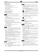
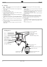
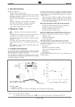
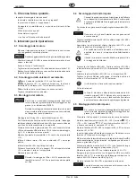
background image

2

P1643E   09/05

140/160PH

Symbole

Warnung!

Dieses Zeichen warnt vor einer
möglicherweise 

gefährlichen

Situation

. Wird diese Warnung

nicht beachtet, können schwer-
ste Verletzungen auftreten.

Achtung!

Dieses Zeichen bezeichnet eine
möglicherweise 

schädliche Si-

tuation

. Wird dieser Hinweis

nicht beachtet, können das Pro-
dukt oder Teile davon beschä-
digt werden.

Hinweis!

Die Zahl im Quadrat ist ein Ser-
vice-Hinweis. Hier werden zu-
sätzliche Informationen für die
richtige Demontage und Monta-
ge gegeben.Die Hinweise wer-
den unter 10. Hinweise erklärt.

Symbols

Warning!

This symbol identifies the poten-
tial for a 

hazardous situation

.

If this warning is not followed, a
serious injury could occur.

Caution!

Caution!

Caution!

This symbol identifies the poten-
tial for a 

damaging situation

.  If

a caution note is not followed,
the product or parts of the prod-
uct could be damaged.

Note!

The number in a square indi-
cates a service note. Additional
information is provided for dis-
assembly and assembly in sec-
tion 10.

Diese Betriebsanleitung vor dem Auspacken
und vor Inbetriebnahme des Werkzeugs le-
sen und genau beachten! Der Schrauber darf
nur von Personen benutzt, gewartet und in-
standgesetzt werden, die mit den Sicherheits-
hinweisen und der Betriebsanleitung vertraut
sind. Die örtlichen Sicherheitsvorschriften be-
züglich Installation, Betrieb und Wartung sind
stets zu befolgen.

Sicherheit

Nehmen Sie den Schrauber erst in Betrieb,
wenn Sie die Sicherheitshinweise und Bedie-
nungsanleitungen gelesen und voll verstan-
den haben.

Read and carefully observe these operating
instructions before unpacking and operating
the tool! The tool must be operated, main-
tained and repaired exclusively by persons
familiar with the operating instructions. Local
safety regulations regarding installation, op-
eration and maintenance must be followed.

Safety

Only operate this tool after safety instructions
and this service manual are fully understood.

Lisez et observez ce manuel d'instructions
avant déballage et mise en marche de l'outil.
Cet outil ne doit être utilisé, entretenu et réparé
que par du personnel qui est familier avec ces
instructions de service. Les consignes de
sécurité en vigueur dans le pays de l'utilisateur
doivent être obligatoirement respectées par
toute personne chargée de l'installation, le
fonctionnement et la maintenance de l'outil.

Sécurité

Lire d'abord attentivement les consignes de
sécurité et le mode d'emploi spécifique à ce
type d'outil et uniquement faire fonctionner
l'outil lorsque son utilisation a été parfaitement
comprise.

Symboles

Signal de danger!

Ce signe vous met en garde
contie une situation dangereuse

.

Des blessures graves peuvent
s'en suivre, si cet avertissement
n'est pas respecté.

Attention!

Attention!

Attention!

Ce signe qualifie une


situation

pouvant potentiellement provo-
quer un


endommagement

.

Le produit ou ses composants
peuvent être détériorés, si les
consignes ne sont pas
respectées.

Annotations

Le chiffre encadré indique une
annotation de service. Ici on vous
donne de plus amples
informations sur le montage et le
démontage correct. Ces
annotations sont expliquées
dans chapitre 10.

Inhaltsverzeichnis

1.

Technische Daten

2

2.

Produktbeschreibung

3

3.

Drehmomenteinstellung

3

4.

Inspektion und Wartung

3

5.

Was tun, wenn..

4

6.

Reparaturanleitung

4

6.1 Demontage des Motors

4

6.2 Demontage des Einschaltventils

4

6.3 Montage des Motors

4

6.4 Demontage der Impuls-Einheit

4

6.5 Montage der Impuls-Einheit

4

6.6 Ölbefüllung

5

Öl-Befülleinrichtung <A>

5

6.7 Öl-Nachbefüllung

5

7.

Ersatzteil-Zeichnung

20

7.

Ersatzteil-Bestelliste

25

8.

Montagehinweise

26

9.

Vorrichtungs-Bestelliste

29

10. Hinweise

30

Contents

1.

Technical data

2

2.

Product Description

6

3.

Torque Adjustment

6

4.

Inspection and Maintenance

6

5.

What to Do If...

7

6.

Repair Instructions

7

6.1 Motor Disassembly

7

6.2 Trigger Valve Disassembly

7

6.3 Motor Assembly

7

6.4 Pulse Unit Disassembly

7

6.5 Assembly of the Pulse Unit

7

6.6 Oil Filling

8

6.7 Top up Oil

8

7.

Spare parts exploded view

20

7.

Spare Parts List

25

8.

Assembly instructions

26

9.

Fixtures order list

29

10. Notes

30

Contenu

1.

Données techniques

2

2.

Description produit

11

3.

Réglage du couple

11

4.

Contrôle et maintenance

11

5.

Que faire lorsque ...

12

6.

Instructions de réparation

12

6.1 Démontage du moteur

12

6.2 Démontage des soupapes de

fermeture

12

6.3 Montage du moteur

12

6.4 Démontage de l’unité d’impulsion

12

6.5 Montage de l'unité d'impulsions

12

6.6 Remplissage d’huile

13

6.7 Ajoutage d'huile

13

7.

Vue éclatée

20

7.

Liste de pièces de rechange

25

8.

Instructions de montage

26

9.

Liste de commande des dispositifs 29

10. Remarques

30

Содержание 140PH

Страница 1: ...etter Parts Manual P1643E 2006 04 P H Max Kapazit t Rated Capacity Abtrieb Final drive 140 140 Nm Q Schnellwechself Quick change 7 16 160 160 Nm 6 Vierkant Square 3 4 Ausf hrung Style B P Pistolengrif...

Страница 2: ...l utilisateur doivent tre obligatoirement respect es par toute personne charg e de l installation le fonctionnement et la maintenance de l outil S curit Lire d abord attentivement les consignes de s...

Страница 3: ...haber le do y comprendido estas instrucciones y el manual espec fico de este modelo S mbolos Atenci n Este s mbolo indica un situaci n potencial de peligro Pueden producirse lesiones f sicas a las pe...

Страница 4: ...e r f e d i v n o i t a t o r o t o u v a t i c o l e v o c a v n e d a d i c o l e v n e s l u P e s l u p r e s l u p i s l u p m i o s l u p x a m n i m x a m n i m m m g k n i m 3 m Q 5 4 H P 0 4...

Страница 5: ...spektionsarbeiten immer Sicherheitshinweise P1687S und die typspezifische Betriebsanleitung beachten und ver wenden Nachfolgende Inspektions und Wartungsliste enth lt Zeit Kontroll und Wartungshinweis...

Страница 6: ...hnt werden Bei Schnellwechselfutter Ausf hrung zuerst 95 91 entfer nen Sprengring 35 90 demontieren Impulseinheit 36 63 aus dem Geh use 62 89 ziehen Hydr Zylinder 44 71 an Schl sselfl chen in glatten...

Страница 7: ...ung C auf das geforderte Drehmoment anziehen 8 Montagehinweise Bild 7 Kugellager 60 87 mit Sicherungsring 59 86 in Geh use 62 89 einbauen O Ring 61 88 einlegen Komplett ber die lange Schaftseite des H...

Страница 8: ...tion tasks The inspection and maintenance list below contains timings checks and maintenance tasks to be carried out when the pulse nutsetter has completed 100 250 and 500 hours of operation Operating...

Страница 9: ...down to room temperature Caution Caution Be sure retaining rings are not extended excessively With quick disconnect attachment first remove 95 91 Remove retaining ring 35 90 Pull pulse unit 36 63 out...

Страница 10: ...threaded ring by the required torque 8 Assembly instructions fig 7 Fit ball bearing 60 87 with the circlip 59 86 into the housing 62 89 Insert the O ring 61 88 Push fully over the long shaft end of t...

Страница 11: ...od le La liste ci contre de contr le et de maintenance indique les consignes de maintenance de contr le et de temps pour 100 250 et 500 heures de service de la visseuse impulsions temps de service tem...

Страница 12: ...sur le filtre 6 4 D montage de l unit d impulsion Seulement autoris si le remplissage avec dispositif de remplissage d huile A a t assur il faut alors adapt l unit d impulsion la temp rature ambiante...

Страница 13: ...on Attention La bague filet e 55 82 ne doit pas se tourner avec Serrer la bague filet e 55 82 au couple demand l aide du dispositif C fig 7 Monter le roulement rainur billes 60 87 avec circlip 59 86 d...

Страница 14: ...di non utilizzo dell avvitatore ad impulsi Durante i lavori di controllo e manutenzione occorre utilizzare e osservare sempre le istruzioni per l uso specifiche e le indicazioni di sicurezza P1687S L...

Страница 15: ...it impulsi Consentito esclusivamente se il riempimento effettuato con il dispositivo di riempimento olio A L unit impulsi deveessereraffreddatafinoaraggiungerelatemperatura ambiente Perilmodelloconpin...

Страница 16: ...58 85 2 9 0 3 Nm Importante Importante La ghiera filettata 55 82 non deve girare insieme con la vite filettata Serrare la ghiera filettata 55 82 con il dispositivo C sul momento torcente richiesto Mon...

Страница 17: ...Manual de Instrucciones espec fico Lasiguientelistadeinspecci nymantenimientocontieneinstrucciones sobre tiempo control y mantenimiento para las 100 250 y las 500 horas de servicio del atornillador de...

Страница 18: ...la pantalla 6 4 Desmontaje de la Unidad de Impulso Esta operaci n s lo se autoriza en caso de disponer de la unidad A para llenado de aceite La temperatura de la unidad de impulso debe ser igual a la...

Страница 19: ...Nm Atenci n Atenci n El anillo roscado 55 82 no debe girar Apriete el anillo roscado 55 82 hasta alcanzar el par de giro deseado 8 Instrucciones para el montaje esquena 7 Monte cojinete 60 87 y el an...

Страница 20: ...o Despiece de Recambios Teil des Motor Service Kits 542323 Included in motor service kit 542323 Comprise dans le motor service kit 542323 Contenuto nel motor service kit 542323 Viene con la motor serv...

Страница 21: ...u s e d r e i r t i d o i c n a g e n o i s n e p s o s r o d a g l o c 5 1 2 2 4 8 1 9 1 r e d e f k c u r D g n i r p s n o i s s e r p m o c n o i s s e r p t r o s s e r i d a l l o m e n o i s s...

Страница 22: ...dillo Teil des Hydraulik Service Kits 542320 Included in hydraulic service kit 542320 Comprise dans le hydraulique service kit 542320 Contenuto nel service kit idraulico 542320 Viene con la service ki...

Страница 23: ...s s e r p m o c n i s e r p m o c e d e l l e u m 7 3 2 2 X 3 4 0 X 0 8 2 7 4 4 0 3 2 3 9 2 e l l e m a L r d y H e d a l b c i l u a r d y h e u q i l u a r d y h e t t e l a p a c i l u a r d i a t...

Страница 24: ...des ditions derni re 11 99 Modificazioni rispetto l ultima edizione Cambios despu s de la ltima edici n Teil des Hydraulik Service Kits 542320 Included in hydraulic service kit 542320 Comprise dans l...

Страница 25: ...t n o c i d a t t e l a p l p c l p c l o r t n o c e d a t e l a p 7 7 9 0 3 2 3 9 1 l p k e l l e m a l r e u e t S m s a e d a l b l o r t n o c l p c e l r t n o c e m a l o l l o r t n o c i d a...

Страница 26: ...Einheit Dismounting of the pulse unit D montage de l unit d impulsion Smontaggio dell unti idraulica Desmontaje de la unidad de impulso L sen des Lagerrings 55 82 Loosen the bearing ring 55 82 D serr...

Страница 27: ...impulso 55 82 C Anzugsmoment 300 Nm 40 Nm Tightening torque 221 lbf ft 29 lbf ft Couple de serrage Coppia di avvitatura Par de apriete Anziehen des Lagerrings 55 82 Tightening of the bearing ring 55...

Страница 28: ...ee dimension X Enfoncer le palier voir X Piantare i cucinetti vede X Empujar el rodamiento ver X 8 X 0 02 0 06 mm 0 0008 0 0024 in X 30 25 26 D1 D2 D3 3 Rotor auspressen Rotor disassembly D monter le...

Страница 29: ...t a s n i e l e s s l h c s k c e t S t e k c o s e l l i u o d l c a l o s s u b a e v a i h c e d e v a l l e d o g e u j o s a v D 0 7 2 3 3 9 l e i p s l a i x A g n u t h c i r r o V l a i x a r...

Страница 30: ...l p u o c a r u s u i h c i d a i p p o c e t e i r p a e d r a p m N l e s s l h c S y e k l c e v a i h c e v a l l t r e w t h c i R r e n e l h o f p m e e u l a v x o r p p a e v i t a c i d n i...

Страница 31: ......

Страница 32: ...2 802 1718 Fax 425 497 0496 Fax 717 757 5063 Tel 905 501 4785 Fax 905 501 4786 Germany England France China Cooper Power Tools Cooper Power Tools Cooper Power Tools SAS Cooper China Co Ltd GmbH Co OHG...

Отзывы: