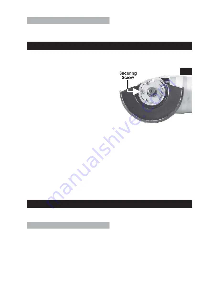
The blade guard can be rotated about its axis
and is locked by a single hex head screw (see
Fig.3). Slacken the screw, using the tool supplied,
grasp the guard firmly and move to the desired
position, ensuring maximum protection for the
operator without impeding the work being
carried out. The screw must be tightened when
the guard is in the desired position.
NOTE: When the tool is new, it may be necessary
to slacken the three cross head screws, in
addition to the securing screw, in order to free
off the guard. This can only be achieved with
the cutting disc removed. Once the guard has
been moved, the three screws must be retightened, and should not require slackening
for this purpose again. Before fitting the cutting disc, try moving the guard again ensuring
only the locking screw is loose, then with the guard in the desired position, retighten the
locking screw.
The hand holding the tool body will control the ON/OFF trigger switch, whilst the other
hand grasps the hand grip and guides the tool over the workpiece.
Hold the tool firmly but not tightly. Allow the tool to do the work...DO NOT force the wheel
on to the workpiece.
The ON/OFF trigger switch (A) in Fig 1, is provided with a safety lock button (B), to
prevent accidental starting. To operate, fully depress the trigger switch and depressing
the safety lock button (B). To stop, release the lock button, and the trigger switch. The
grinder will slow down and stop.
MAINTENANCE
IMPORTANT: Before carrying out any maintenance tasks, ALWAYS disconnect the tool
from the mains electrical supply.
Before Each Use
1.
Always inspect the tool before use and ensure it is in top condition.
2.
Ensure all air vents are clear, use compressed air to clean the tool where possible.
(Always wear protective goggles when cleaning with compressed air.). Take all necessary
precautions regarding the use of compressed air.
3.
Check the power cable to ensure it is sound and free from cracks, bare wires etc.
4.
Ensure the grinding wheel or cutting disc is perfectly sound, free from cracks or damage
in any way.
8
OPERATION
IMPORTANT
: DO NOT plug the tool in to the mains, unless you have ensured it is switched
OFF and the guard is set to the desired position.
2. Hand Grip
A threaded hole ‘E’, on the top, left or right hand side of the gear housing, is provided so
that the hand grip may be screwed in, as required, to provide left or right hand control
of the tool.
Fig 3.
Whenever changing discs, always run the grinder at no load speed to check for
irregularities before beginning work.


