7
WARNING:
NEVER press the spindle lock button when starting the tool, and
NEVER press the button when the tool is operating.
DO NOT press thebutton until the wheel/disc has stopped completely
ASSEMBLY
1. Mounting the Grinding Wheel/Cutting Disc
Fig 1.
FEATURES
(Ref. Fig 1)
1.1
Unscrew and remove the outer flange by locking
the spindle using the Spindle Lock button then
usethe flange tool supplied to turn the flange (right
hand thread). It may then be screwed off by
hand.
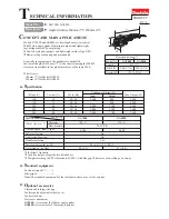
1.2 The grinding wheel supplied is the ‘Depressed
Centre’type. Mount it as shown in the Fig.2. i.e.
with the depressed centre towards the motor
1.3 Ensuring the wheel sits snugly over the raised boss on
the inner flange, screw on the outer flange with the
centre boss facing inwards.
1.4 Tighten the flange using the tool provided, locking
the spindle by pressing the Spindle Lock button,
andtaking care to ensure the wheel is still sitting
snugly,centred over the flange bosses. Care should
be taken also NOT to overtighten the outer flange.
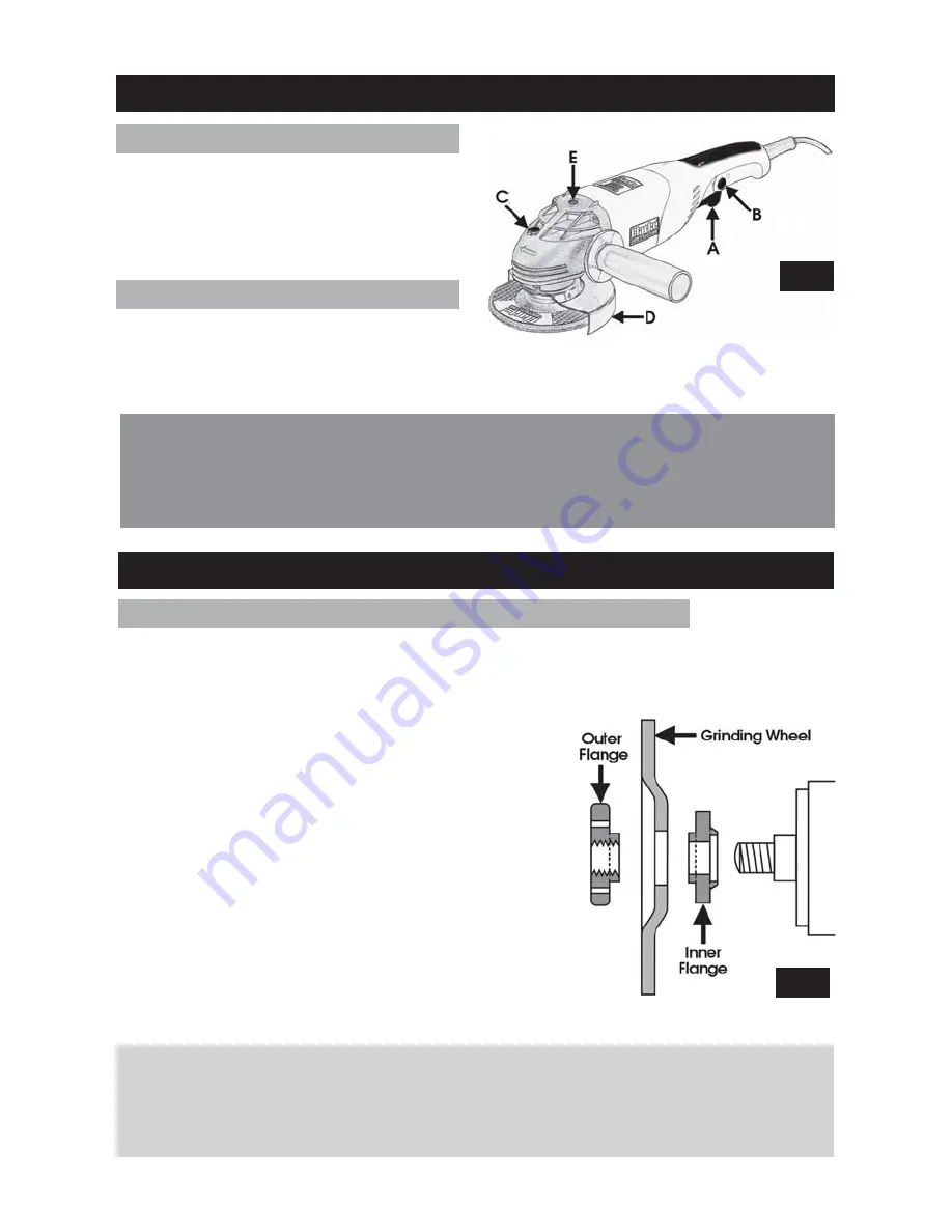
1. ON/OFF Switch (A)
The ON/OFF switch (A) is provided with a safety
lock button (B). The lock button (B) must be
held in before the trigger can be squeezed in
to the ‘ON’ position. This is designed to prevent
accidental starting.
.
2. Spindle Lock Button (C)
WARNING:
Fig 2 shows the set up for a grinding wheel.
When attaching a cutting or diamond disc YOU MUST REVERSE the outer
flange so that the boss faces OUTWARDS.
Ensure the grinder is disconnected from the mains supply.
Fig 1.
Fig 2.
When pressed, this button, located on top
of the head, is used to lock the spindle
when attempting to unscrew and remove the outer flange (using the special tool
provided), in order to mount or change the grinding wheel or cutting disc.


