


16-17
Cisco ONS 15454 DWDM Installation and Operations Guide, R6.0
April 2006
Chapter 16 Card Reference
16.2.4 AIC-I Card
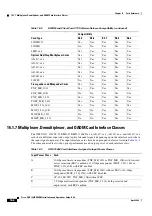
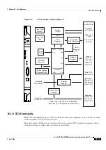
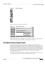
Figure 16-3
AIC-I Faceplate and Block Diagram
16.2.4.1 AIC-I Card-Level Indicators
describes the eight card-level LEDs on the AIC-I card faceplate.
AIC-I
Fail
Express orderwire
Local orderwire
EEPROM
LED x2
AIC-I FPGA
SCL links
4 x
IN/OUT
Power
Monitoring
12/16 x IN
Ringer
Act
Ring
Ring
Input
Output
78828
FAIL
ACT
ACC
INPUT/OUTPUT
EOW
LOW
RING
AIC-1
(DTMF)
(DTMF)
UDC-A
UDC-B
DCC-A
DCC-B
ACC
PWR
A
B
RING
DCC-B
DCC-A
UDC-B
UDC-A
Table 16-11
AIC-I Card-Level Indicators
Card-Level LEDs
Description
Red FAIL LED
Indicates that the card’s processor is not ready. The FAIL LED is on during
reset and flashes during the boot process. Replace the card if the red FAIL
LED persists.
Green ACT LED
Indicates the AIC-I card is provisioned for operation.
Содержание ONS 15454 DWDM
Страница 38: ...Figures xxxviii Cisco ONS 15454 DWDM Installation and Operations Guide R6 0 August 2005 ...
Страница 54: ...Procedures liv Cisco ONS 15454 DWDM Installation and Operations Guide R6 0 August 2005 ...
Страница 64: ... 64 Cisco ONS 15454 DWDM Installation and Operations Guide R6 0 August 2005 Chapter ...


