


Connecting the Input/Output Signals
29
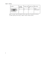
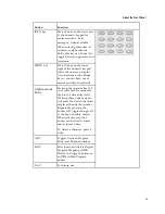
Cue Tone/Cue Trigger Interface
The D9824 receiver is equipped with a connector labeled Cue Tone/Relay for alarm
relay outputs for remote alarm signaling. This connector provides Cue Tone, Cue
Trigger and Alarm relay functionality. These outputs are user-configurable via the
Setup Menu on the front panel.
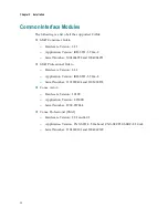
The connector is a 15-pin sub-D female connector. The following diagram shows the
connector and the pin allocation table for Cue Tone, Cue Trigger and Alarm relay
connections.
Connector
Pin
Pin allocation
1
Cue Trig 1
2
Cue Trig 2
3
Cue Trig 3
4
Cue Trig 4
5
Cue Trig 5
6
Cue Trig 6
7
Cue Trig 7
8
Cue Trig 8
9
Not connected
10
Alarm - Ground
11
Alarm - Normally open
12
Chassis ground
13
Cue Tone -
14
Cue Tone +
15
Alarm - Normally closed
Connecting the Cue Tone Interface
Connect the Cue Tone pins, 13 and 14 to a device to facilitat e ad-insertion using
DTMF Analog Cue Tones.
Connecting the Cue Trigger Interface
Connect the Cue Trigger pins (1 to 8) to up to 8 serial control devices or a device to
control ad-insertion. These outputs are user-configurable on the front panel menu.
Содержание D9824
Страница 22: ......
Страница 26: ...Chapter 1 Introduction 4 On Screen Display support on baseband output NIT Retune Recovery ...
Страница 40: ......
Страница 164: ......
Страница 306: ......
Страница 368: ......
Страница 370: ......
Страница 388: ......
Страница 410: ...Appendix C Compliance 388 Declarationof Conformity ...
Страница 415: ......


