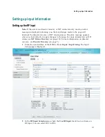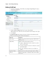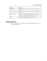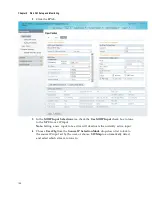
Setting up Input Information
153
14
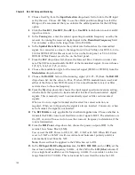
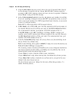
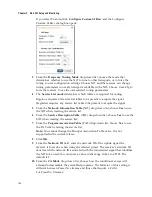
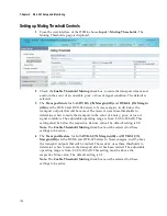
For RF1, RF2, RF3, and/or RF4, set the higher oscillator frequency, in GHz, of the
LNB in the
LO2 (Ghz)
column. If it is a single band oscillator, set this value to
0.0. You can enter a value in a range from 0.0 to 15.0 GHz. This value must be
higher than the value for LO1. In single-band LNB applications, set this value to
0.0.
15
In the
Crossover
field, enter the crossover
frequency for RF1, RF2, RF3, and/or
RF4. This is an internal threshold frequency used for selecting the LO1 or LO2
frequency, depending on the current downlink frequency settings. This option is
only used in dual-band LNB applications.
You can enter a value in a range from 0.0 to 15.0 GHz. In single-band LNB
applications, set this value to 0.0.
16
Choose the signal polarisation setting (Horizontal, Vertical, or Automatic) from
the
Polarisation
drop-down list. This setting is only applicable when the LNB
Power is set to H-NIT or V-NIT. It marks the polarity of the signal connected to
the current RF input.
17
Enter the Orbital Position (
Orbital Posn
) for RF1, RF2, RF3, and/or RF4, in
degrees. This is the location in orbit of the satellite currently being used. The
satellite position (in degrees) in combination with the direction (either E (East) or
W (West)) denotes the satellite position the dish connected to the current RF
Input should point. This is used when the satellite is not available in the look-up
menu list.
For manual configuration, enter the location of the satellite using the numerical
keypad. The receiver will not recognize the satellite name and identify it as
Unknown. This setting is required to resolve any ambiguity between RF inputs
during automatic disaster recovery.
18
Choose the east/west flag for RF1, RF2, RF3, or RF4 from the
East/West Flag
drop-down list. This is the satellite position the dish connected to the current RF
Input should point. The options are East, West, or N/A (Not Applicable).
19
Click
Apply
.
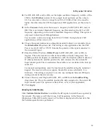
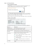
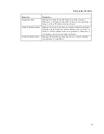
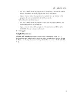
Validating the Orbital Position
Click
Validate Orbital Position
to validate the RF inputs to match those expected by
the network. The receiver will check to see if all frequencies in the Network
Information Table (NIT) can be tuned to. The Date is displayed as the last date that
the Validate operation was performed.
Содержание D9824
Страница 22: ......
Страница 26: ...Chapter 1 Introduction 4 On Screen Display support on baseband output NIT Retune Recovery ...
Страница 40: ......
Страница 164: ......
Страница 306: ......
Страница 368: ......
Страница 370: ......
Страница 388: ......
Страница 410: ...Appendix C Compliance 388 Declarationof Conformity ...
Страница 415: ......

