background image

5-14

Cisco 2900 Series and 3900 Series Hardware Installation Guide

OL-18712-03

Chapter 5      Installing and Upgrading Internal Modules and FRUs

  Installing and Removing DRAM DIMMs

Removing a DRAM DIMM

Follow these steps to remove a DRAM DIMM:

Step 1

Read the 

“Safety Warnings” section on page 5-2

 section and disconnect the power supply before you 

perform any module replacement.

Step 2

Remove the chassis cover. For Cisco 2900 series ISRs, see the 

“Removing and Replacing the Chassis 

Cover” section on page 5-4

. For Cisco 3900 series ISRs, see the 

“Removing and Replacing the Services 

Performance Engine” section on page 5-6

.

Step 3

Locate the DRAM DIMM module. See the 

“Locating Internal Modules” section on page 5-7

 to find the 

DRAM DIMM sockets on the router.

Step 4

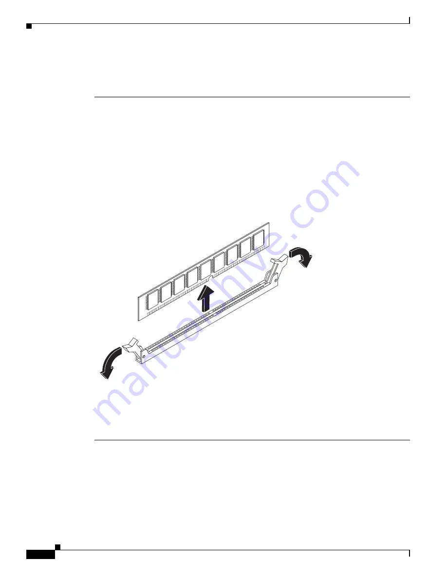
Pull the latches away from the DRAM DIMM at both ends to lift the DIMM slightly. Pull the DIMM out 
of the socket as shown in 

Figure 5-9

.

Figure 5-9

Removing a DRAM DIMM

Step 5

Place the DIMM in an antistatic bag to protect it from ESD damage.

Step 6

Replace the chassis cover. For Cisco 2900 series ISRs, see the 

“Removing and Replacing the Chassis 

Cover” section on page 5-4

. For Cisco 3900 series ISRs, see the 

“Removing and Replacing the Services 

Performance Engine” section on page 5-6

.

250945

Содержание Cisco 2900 series

Страница 1: ...as more than 200 offices worldwide Addresses phone numbers and fax numbers are listed on the Cisco website at www cisco com go offices Cisco 2900 and 3900 Series Hardware Installation Last Revised November 4 2013 Text Part Number OL 18712 01 ...

Страница 2: ... correct the interference by using one or more of the following measures Reorient or relocate the receiving antenna Increase the separation between the equipment and receiver Connect the equipment into an outlet on a circuit different from that to which the receiver is connected Consult the dealer or an experienced radio TV technician for help Modifications to this product not authorized by Cisco ...

Страница 3: ...onal Help Locating Labels on the Router 1 16 Hardware Features 1 17 Built in Interface Ports 1 17 Gigabit Ethernet Ports 1 17 USB Serial Console Port 1 18 Removable and Interchangeable Modules and Cards 1 18 Services Performance Engine 1 21 Service Modules 1 21 Enhanced High Speed WAN Interface Cards 1 21 Integrated Service Modules 1 22 Packet Voice Data Modules 1 22 Memory 1 22 Power Supplies 1 2...

Страница 4: ...1 CSU DSU Connections 2 12 Required Tools and Equipment for Installation and Maintenance 2 12 Installation Checklist 2 14 Creating a Site Log 2 15 C H A P T E R 3 Installing and Connecting the Router 3 1 What you Need to Know 3 3 Before you Begin 3 3 Unpacking the Router 3 4 Installing the Router 3 4 Rack Mounting the Chassis 3 5 Attaching Rack Mount Brackets to Cisco 2901 Routers 3 5 Attaching Ra...

Страница 5: ...USB Device Driver 3 35 Installing the Cisco Microsoft Windows XP USB Driver 3 35 Installing the Cisco Microsoft Windows 2000 USB Driver 3 36 Installing the Cisco Microsoft Windows Vista USB Driver 3 36 Uninstalling the Cisco Microsoft Windows USB Driver 3 37 Uninstalling the Cisco Microsoft Windows XP and 2000 USB Driver 3 37 Uninstalling the Cisco Microsoft Windows Vista USB Driver 3 37 Connectin...

Страница 6: ...rnings 5 2 Accessing Internal Modules 5 4 Removing and Replacing the Chassis Cover 5 4 Removing and Replacing the Services Performance Engine 5 6 Locating Internal Modules 5 7 Installing and Removing DRAM DIMMs 5 13 Locating and Orienting DRAM DIMM 5 13 Removing a DRAM DIMM 5 14 Installing a DRAM DIMM 5 15 Installing and Removing ISMs 5 16 Software Requirement for ISMs 5 17 Locating an ISM 5 17 Re...

Страница 7: ... DC Power Supply 5 41 Installing and Removing a Redundant Power Supply Adapter 5 42 Installing an RPS Adapter 5 43 Removing an RPS Adapter 5 43 Replacing a Fan Tray or Air Filter 5 45 Replacing the Cisco 2911 Fan Tray 5 45 Replacing the Cisco 2911 Air Filter 5 46 Replacing the Cisco 2921 or 2951 Fan Tray 5 47 Replacing the Cisco 3900 Series Fan Tray 5 48 Replacing the Cisco 3900 Series Air Filter ...

Страница 8: ...Contents 6 Cisco 2900 Series and 3900 Series Hardware Installation Guide OL xxxxx xx Removing a Voice Module A 2 Inserting a Data or Voice Module A 2 Hot Swapping Procedures A 3 ...

Страница 9: ...mation may not apply to your specific router model Note For warranty service and support information see the Cisco Warranty Terms section in the Readme First for the Cisco 1900 Series 2900 Series and 3900 Series Integrated Services Routers document that was shipped with your router Audience This guide is intended for Cisco equipment providers and service persons who are technically knowledgeable a...

Страница 10: ...ter Describes how to install and connect the router to LAN WAN and Voice networks 4 Configuring the Router Describes how to power up the router and perform the initial configuration 5 Installing and Upgrading Internal Modules and FRUs Describes how to install and upgrade internal modules and field replaceable units3 on the router 6 Getting Software Licenses for the Router Describes how to purchase...

Страница 11: ...nt italic font Document titles new or emphasized terms and arguments for which you supply values are in italic font Elements in square brackets are optional x y z Required alternative keywords are grouped in braces and separated by vertical bars x y z Optional alternative keywords are grouped in brackets and separated by vertical bars string A nonquoted set of characters Do not use quotation marks...

Страница 12: ...istoa huomioi sähköpiirien käsittelemiseen liittyvät riskit ja tutustu onnettomuuksien yleisiin ehkäisytapoihin Turvallisuusvaroitusten käännökset löytyvät laitteen mukana toimitettujen käännettyjen turvallisuusvaroitusten joukosta varoitusten lopussa näkyvien lausuntonumeroiden avulla SÄILYTÄ NÄMÄ OHJEET Attention IMPORTANTES INFORMATIONS DE SÉCURITÉ Ce symbole d avertissement indique un danger V...

Страница 13: ...ção que poderá ser causadora de lesões corporais Antes de iniciar a utilização de qualquer equipamento tenha conhecimento dos perigos envolvidos no manuseio de circuitos elétricos e familiarize se com as práticas habituais de prevenção de acidentes Utilize o número da instrução fornecido ao final de cada aviso para localizar sua tradução nos avisos de segurança traduzidos que acompanham este dispo...

Страница 14: ...vi Cisco 2900 Series and 3900 Series Hardware Installation Guide OL 18712 02 ...

Страница 15: ...ação fornecido ao final de cada aviso para localizar sua tradução nos avisos de segurança traduzidos que acompanham o dispositivo GUARDE ESTAS INSTRUÇÕES Advarsel VIGTIGE SIKKERHEDSANVISNINGER Dette advarselssymbol betyder fare Du befinder dig i en situation med risiko for legemesbeskadigelse Før du begynder arbejde på udstyr skal du være opmærksom på de involverede risici der er ved elektriske kr...

Страница 16: ...viii Cisco 2900 Series and 3900 Series Hardware Installation Guide OL 18712 02 ...

Страница 17: ...nly with the same or equivalent type recommended by the manufacturer Dispose of used batteries according to the manufacturer s instructions Statement 1015 Warning Do not use this product near water for example near a bath tub wash bowl kitchen sink or laundry tub in a wet basement or near a swimming pool Statement 1035 Warning Never install telephone jacks in wet locations unless the jack is speci...

Страница 18: ...adios Regulatory Compliance and Safety Information for Cisco 2900 Series Integrated Services Routers Regulatory Compliance and Safety Information for Cisco 3900 Series Integrated Services Routers Software Activation Software Activation for Cisco Integrated Services Routers Cisco IOS Software Activation Configuration Guide Configuration Cisco CP Express User s Guide Cisco Internet Operating System ...

Страница 19: ... files simultaneously and to change case sensitivity and other options The Adobe Reader online help has more information about how to search PDF documents Obtaining Documentation and Submitting a Service Request For information on obtaining documentation submitting a service request and gathering additional information see the monthly What s New in Cisco Product Documentation which also lists all ...

Страница 20: ...xii Cisco 2900 Series and 3900 Series Hardware Installation Guide OL 18712 02 ...

Страница 21: ...E is provided through the use of add on hardware This series of ISRs have new slots that support next generation Enhanced High Speed WAN Interface Cards EHWICs Internal Services Modules ISMs Packet Voice Data Modules PVDM3s Service Modules SMs and Services Performance Engines SPEs Access to the Cisco Multi Gigabit Fabric MGF facilitates connection between switch ports on the ISR without utilizing ...

Страница 22: ... HWICs voice WAN interface cards VWICs WAN interface cards WICs Internal Services Modules ISMs and packet voice DSP modules PVDM3s However some router models do not support all of these media types See the router model descriptions for more information Cisco 2900 Series ISRs Cisco 2901 Chassis page 1 2 Cisco 2911 Chassis page 1 4 Cisco 2921 and Cisco 2951 Chassis page 1 6 Cisco 3900 Series ISRs Ci...

Страница 23: ... 100 1000 Ethernet port GE0 0 7 Ground 8 USB0 and USB1 1 Top 9 CompactFlash3 0 and 1 3 Only Advanced Capability CompactFlash CF purchased from Cisco operates in Cisco 2900 series and Cisco 3900 series ISRs Legacy CF can impact and severely degrade performance in these routers See the Memory section on page 1 22 When legacy CF is inserted the following error message appears WARNING Unsupported comp...

Страница 24: ...lash 0 and 1 0 Right 2 ISM1 1 ISM Internal Services Module 3 PVDM3 0 and 1 0 Right 4 EN Enable USB console 5 EN Enable RJ 45 console 6 S Speed 7 L Link ISM PVDM1 PVDM0 EN EN S L USB CONSOLE AUX G E 0 0 DO NOT REMOVE DURING NETWORKING OPERATION DO NOT REMOVE DURING NETWORKING OPERATION CF 1 CF 0 1 0 250962 4 5 6 7 1 EHWIC 3 EHWIC 2 EHWIC 1 EHWIC 0 S L GE 0 1 2901 3 2 1 AC OK1 2 On off switch 3 AC p...

Страница 25: ...0 Right 2 Only Advanced Capability CompactFlash CF purchased from Cisco operates in Cisco 2900 series and Cisco 3900 series ISRs Legacy CF can impact and several degrade performance in these routers See the Memory section on page 1 22 When legacy CF is inserted the following error message appears WARNING Unsupported compact flash detected Use of this card during normal operation can impact and sev...

Страница 26: ...2951 Routers 1 CompactFlash 0 and 1 0 Far right 2 ISM1 1 Integrated Service Module ISM 3 PVDM3 PVDM 0 1 0 Far right LED 4 EN Enable USB console 5 EN Enable RJ 45 console 6 S Speed 7 L Link ISM EN EN S L S L USB 1 0 CONSOLE AUX GE 0 1 GE 0 2 G E 0 0 250990 2 4 5 6 7 1 EHWIC 3 EHWIC 2 EHWIC 1 EHWIC 0 CF 0 CF 1 PVDM1 PVDM0 3 2911 DO NOT REMOVE DURING NETWORKING OPERATION DO NOT REMOVE DURING NETWORKI...

Страница 27: ... 2951 1 left on 2921 2 Service module slots support legacy network modules when inserted with an adapter See the router product page at Cisco com for a list of supported modules Cisco 2921 supports only one service module in the left slot 11 CompactFlash3 0 and 1 0 Right 3 Only Advanced Capability CF purchased from Cisco operates in Cisco 2900 series and Cisco 3900 series ISRs Legacy CF will not o...

Страница 28: ...0 Back panel slots and connectors Figure 1 13 Back panel LEDs Figure 1 14 1 CompactFlash 0 and 1 0 Right 2 ISM1 1 ISM Internal Services Module 3 PVDM3 0 1 and 2 0 Right 4 EN Enable USB console 5 EN Enable RJ 45 console 6 SFP2 EN 2 SFP small form factor pluggable 7 SFP S 8 S Speed 9 L Link EHWIC 3 EHWIC 2 EHWIC 1 EHWIC 0 CF 1 CF 0 DO NOT REMOVE DURING NETWORKING OPERATION ISM PVDM2 PVDM1 PVDM0 EN E...

Страница 29: ... Front Panel of the Cisco 3900 Series ISRs 1 AC OK1 1 LED goes off if the AC power fails or is disconnected It does not go on and off with the power switch 2 On off switch 3 Power connector 4 SYS status LED 5 ACT status LED 6 POE 7 Boost 8 PS1 Right PS2 Left Cisco 3900 Series SYS ACT POE BOOST PS2 PS1 PS1 PS2 247132 1 2 3 1 2 3 4 5 6 7 8 ...

Страница 30: ...dules when inserted with an adapter See the router product page at Cisco com for a list of supported modules Double wide service modules install in the top slots See Table 1 5 for more router slot and module configurations 4 One single wide in slot 1 lower left Lower right panel cannot be removed See Table 1 5 for more router slot and module configurations 11 CompactFlash5 0 and 1 0 Far right 5 On...

Страница 31: ...lots1 0 1 and 2 0 Far right 2 USB serial console port 3 AUX port 4 RJ 45 serial console port 5 10 100 1000 Ethernet ports GE 0 3 Top GE 0 2 Bottom 6 10 100 1000 Ethernet ports GE 0 1 Top GE 0 0 Bottom ISM EN EN SFP S E N S L S L USB 1 0 CONSOLE AUX GE 0 1 GE 0 2 G E 0 0 SFP S E N DO NOT REMOVE DURING NETWORKING OPERATION DO NOT REMOVE DURING NETWORKING OPERATION C3900 SPE100 K9 PVDM3 PVDM2 PVDM1 P...

Страница 32: ...EHWIC 2 Service module slots support legacy network modules when inserted with an adapter See the router product page at Cisco com for a list of supported modules See Table 1 5 for router slot and module configurations 3 Service module slots support legacy network modules when inserted with an adapter See the router product page at Cisco com for a list of supported modules See Table 1 5 for router...

Страница 33: ...fer to these sections to locate labels on Cisco 2900 series and 3900 series ISRG2 routers Cisco 2900 Series Labels on Cisco 2901 page 1 13 Labels on Cisco 2911 page 1 14 Labels on Cisco 2921 and Cisco 2951 page 1 15 Cisco 3900 Series Labels on Cisco 3925 and Cisco 3945 page 1 15 Labels on Cisco 2901 Figure 1 15 shows the location of the labels on the Cisco 2901 router Figure 1 15 Labels Location o...

Страница 34: ...rial Number PID VID and CLEI Labels on Cisco 2911 Figure 1 16 shows the location of the labels on the Cisco 2911 router Figure 1 16 Labels Location on the Cisco 2911 Router Label Description 1 Product ID 2 Serial Number 3 PID VID 4 CLEI DO NOT REMOVE DURING NETWORK OPERATION DO NOT REMOVE DURING NETWORK OPERATION 250976 2 1 4 3 ...

Страница 35: ...igure 1 17 Label Location on the Cisco 2921 and Cisco 2951 Routers Labels on Cisco 3925 and Cisco 3945 Figure 1 18 shows the two locations where labels are located on Cisco 3900 ISRs There are labels on the router chassis and on the Services Performance Engine SPE Note Use the serial number on the SPE label to obtain a PAK DO NOT REMOVE DURING NETWORK OPERATION DO NOT REMOVE DURING NETWORK OPERATI...

Страница 36: ...ng for models by using a tree structured product hierarchy A search field on the final results page that makes it easier to look up multiple products End of sale products clearly identified in results lists The tool streamlines the process of locating serial number labels and identifying products Serial number information expedites the entitlement process and is important for access to support ser...

Страница 37: ...r chassis Gigabit Ethernet Ports There are two different types of Gigabit Ethernet GE ports available on Cisco 2900 series and Cisco 3900 series ISRs Table 1 4 Summary of Cisco 2900 series and Cisco 3900 series Built In Interfaces Data Ports Management Ports Router Model 10 100 1000 GE RJ 45 10 100 1000 SFP USB Type A Console Serial RJ 45 Console Serial Mini USB Type B Auxiliary RJ 45 Cisco 2901 2...

Страница 38: ...Always use the SFP port but fail over to the RJ 45 port if the SFP port fails USB Serial Console Port The Mini USB type B serial port has been enabled to perform management tasks on the router To use this port you must install a Windows USB device driver before establishing physical connectivity between a personal computer and the router See the Installing the Cisco Microsoft Windows USB Device Dr...

Страница 39: ...s lines must be disconnected 1 before unplugging the main power connector or 2 while the housing is open or both Statement 1043 See the Overview of Cisco Network Modules and Service Modules for Cisco Access Routers document for general information and single and double wide slot numbering See the Installing Cisco Network Modules in Cisco Access Routers document for instructions that describe how t...

Страница 40: ...2 2 EHWIC slots support HWICs WICs and VICs ISM3 3 AIMs are not supported PVDM34 2901 4 single wide EHWIC or 2 double wide DW EHWIC 1 2 2911 1 single wide 4 single wide EHWIC or 2 double wide DW EHWIC 1 2 2921 1 single wide or 1 double wide 4 single wide EHWIC or 2 double wide DW EHWIC 1 3 2951 2 single wide or 1 double wide 4 single wide EHWIC or 2 double wide DW EHWIC 1 3 3925 Services Performan...

Страница 41: ...on Cisco 2900 series and Cisco 3900 series ISRs With the largest form factor and power capacity these modules deliver high performance service applications SMs are physically larger than legacy network modules as a result network modules require an adapter for installation See the Installing Cisco Network Modules in Cisco Access Routers guide for installation instructions http www cisco com en US ...

Страница 42: ...nning configuration and routing tables and is used for packet buffering by the network interfaces Cisco IOS software executes from DRAM memory Supported module types are Unregistered Dual In Line Memory Module UDIMM and very low profile registered DIMM VLP RDIMM Note UDIMMs and VLP RDIMMs are not interchangeable Boot NVRAM 256K of internal non volatile memory Stores the bootstrap program ROM monit...

Страница 43: ...C memory 512 MB Maximum memory 2 5 GB Cisco 2911 Expansion Type UDIMM with ECC UDIMM sizes 512 MB 1 GB 2GB UDIMM expansion slots 1 Fixed onboard ECC memory 512 MB Maximum memory 2 5 GB Cisco 2921 Expansion Type UDIMM with ECC UDIMM sizes 512 MB 1 GB 2 GB UDIMM expansion slots 1 Fixed onboard ECC memory 512 MB Maximum memory 2 5 GB Cisco 2951 Expansion Type VLP RDIMM with ECC VLP RDIMM sizes 512 MB...

Страница 44: ...POE power rates Cisco 3945 Type VLP RDIMM with ECC VLP RDIMM sizes 512 MB and 1 GB VLP RDIMM expansion slots 2 both must be the same density Default VLP RDIMM memory modules Two 512 MB modules for a maximum of 1 GB Maximum memory 2 0 GB 1 0 GB in each slot Cisco 3925E Type VLP RDIMMwith ECC VLP RDIMM sizes 512 MB 1GB VLP RDIMM expansion slots 2 both must be the same density Default ECC memory modu...

Страница 45: ... new one See the Replacing a Fan Tray or Air Filter section on page 5 45 Fan speeds are controlled by the fan speed controller circuitry To minimize noise the fans operate at one of several predetermined speeds and are dependent on the input ambient air temperature 3945 X X X X X X X 3945E X X X X X X X 1 Must have RPS or POE boost installed 2 Internal RPS means that and additional power supply ca...

Страница 46: ...w Figure 1 22 shows the Cisco 3900 series standard non NEBS airflow configuration For NEBS the airflow is reversed Figure 1 23 shows the Cisco 3900 series standard NEBS airflow configuration Figure 1 19 Cisco 2901 Router Airflow Figure 1 20 Cisco 2911 Router Airflow Figure 1 21 Cisco 2921 and Cisco 2951 Router Airflow 250960 SYS ACT POE Cisco 2900 Series 250975 Cisco 2900 Series SYS ACT SYS PWR1 A...

Страница 47: ...for the life time of the router under the operating environmental conditions specified for the router and is not field replaceable Note If the lithium battery in a Cisco 2900 or Cisco 3900 series ISR should fail the router must be returned to Cisco for repair Although the battery is not intended to be field replaceable the following warning must be heeded Warning There is the danger of explosion i...

Страница 48: ... ports is defined as follows interface type 0 slot port 0 indicates slots that are built into the chassis of a router On the Cisco 2901 router all slots begin with 0 because all slots are built into the chassis On the Cisco 2911 2921 2951 and Cisco 3900 series routers some slots are built into the chassis and some are external Slots that are part of a network module or an extension voice module ha...

Страница 49: ... only to Cisco 2921 router 5 Applies only to Cisco 2951 Cisco 3925 and Cisco 3925E routers 6 Applies only to Cisco 3945 and Cisco 3945E routers 7 Applies only to Cisco 2951 Cisco 3925 and Cisco 3925E routers 8 Applies only to Cisco 3945 and 3945E routers Table 1 11 Slot Port and Interfaces continued Slots Ports Interface 29011 2911 2921 2951 3925 3945 3925E 3945E Table 1 12 Interface Numbering on ...

Страница 50: ...e 0 Port numbers are 16 to 19 in expansion module 1 voice port 2 0 x BRI interface in a BRI expansion module internal slot in an extension voice module Interface type 2 port Port numbers are 0 to 3 if one expansion module is installed Port numbers are 0 to 7 if two expansion modules are installed interface bri 2 x 1 Interface abbreviations fa Fast Ethernet gi Gigabit Ethernet USB universal serial ...

Страница 51: ...ng engine and any I O port Front bezel Front bezel Off No packet transfers are occurring RJ 45 CON Green Serial console is active Back panel Back panel USB CON Green USB console is active Back panel Back panel GE Link Green Solid green indicates the Ethernet port has a link partner Back panel Back panel SFP S Blinking green Blinking frequency indicates port speed See the definition for the S LED B...

Страница 52: ...blished Back panel Back panel Off No FE or GE link is established PVDM 0 1 2 and 3 Green PVDM is initialized Back panel Back panel Amber PVDM is detected but not initialized Back panel Back panel Off No PVDM installed Back panel Back panel ISM Green Initialized Amber Initialized with error Off Not installed 1 LED goes off if the AC power fails or is disconnected It does not go on and off with the ...

Страница 53: ...C input power Input voltage 100 to 240 VAC autoranging Frequency 47 to 63 Hz Input current 0 3 A to 1 5 A configuration dependent Input current with AC POE 0 3 to 3 4 A configuration dependent Surge current 30 A maximum at 115 VAC 60Hz 60 A maximum at 230 VAC 50 Hz Power consumption 55 W to 145 W 188 to 495 BTU hr configuration dependent With AC POE 60 W to 330 W 205 to 1126 BTU hr configuration d...

Страница 54: ... Power Typ Max 49 61 dBA Regulatory Safety compliance IEC 60950 1 Safety of information technology equipment EN 60950 1 Safety of information technology equipment UL 60950 1 Standard for safety for information technology equipment US CAN CSA C22 2 No 60950 1 Safety of information technology equipment including electrical business equipment Canada AS NZS 60950 1 2003 IEC60950 3rd edition PRC IEC609...

Страница 55: ...PR22 Class A VCCI Class A SD EMI Class A Harmonic Current Emission EN61000 3 2 for EUT Power requirements 16A EN61000 3 12 for EUT Power requirements 16A Voltage Fluctuation and Flicker EN61000 3 3 for EUT Power requirements 16 EN61000 3 11 for EUT Power requirements 16A For detailed compliance information see the Regulatory Compliance and Safety Information for Cisco 2900 Series Integrated Servic...

Страница 56: ...ompliant 2 5 W 500 mA max 1 10 100 1000 Gigabit Ethernet Three RJ 45 connectors GE0 0 GE0 1 GE0 2 auto MDIX2 Environmental Operating humidity 5 to 85 RH Operating humidity short term per NEBS 5 to 90 but not to exceed 0 024 kg water kg of dry air Operating temperature up to 5906 ft 1800 m elevation 32 to 104 F 0 to 40 C Operating temperature up to 9843 ft 3000 m elevation 32 to 104 F 0 to 40 C Ope...

Страница 57: ...1 Standard for safety for information technology equipment US CAN CSA C22 2 No 60950 1 Safety of information technology equipment including electrical business equipment Canada AS NZS 60950 1 2003 IEC60950 3rd edition PRC IEC60950 2nd Edition Mexico For detailed compliance information see the Regulatory Compliance and Safety Information for Cisco 2900 Series Integrated Services Router document Tab...

Страница 58: ...S NZS CISPR22 Class A VCCI Class A SD EMI Class A Harmonic Current Emission EN61000 3 2 for EUT Power requirements 16A EN61000 3 12 for EUT Power requirements 16A Voltage Fluctuation and Flicker EN61000 3 3 for EUT Power requirements 16 EN61000 3 11 for EUT Power requirements 16A For detailed compliance information see the Regulatory Compliance and Safety Information for Cisco 2900 Series Integrat...

Страница 59: ...liary port RJ 45 connector USB ports Two USB Type A USB 2 0 compliant 2 5 W 500 mA max 1 10 100 1000 Gigabit Ethernet Three RJ 45 connectors GE0 0 GE0 1 GE0 2 auto MDIX SFP One RJ 45 connector supports an SFP module When an SFP module is installed the adjacent RJ 45 GE connector is disabled Environmental Operating humidity 10 to 85 RH Operating temperature up to 5906 ft 1800 m elevation 32 to 104 ...

Страница 60: ...TE Immunity characteristics Limits and methods of measurement EN 50082 1 Electromagnetic compatibility Generic immunity standard Part 1 EN 300 386 Electromagnetic compatibility for TNE SD EMI EN 61000 6 1 For detailed compliance information see the Regulatory Compliance and Safety Information for Cisco 2900 Series Integrated Services Routers document EMC compliance EN 55022 class A CISPR22 class A...

Страница 61: ...n 12 Arms per half cycle Power consumption 75 to 320 W 256 to 1092 BTU hr configuration dependent With AC POE 80 to 750 W 273 to 753 BTU hr configuration dependent Ports Console port One RJ 45 connector and one mini USB Type B USB 2 0 compliant Auxiliary port RJ 45 connector USB ports Two USB Type A USB 2 0 compliant 2 5 W 500 mA max 1 10 100 1000 Gigabit Ethernet Three RJ 45 connectors GE0 0 GE0 ...

Страница 62: ... Sound Power Typical Maximum 62 6 to 74 5 dBA Regulatory Safety compliance IEC 60950 1 Safety of information technology equipment EN 60950 1 Safety of information technology equipment UL 60950 1 Standard for safety for information technology equipment US CAN CSA C22 2 No 60950 1 Safety of information technology equipment including electrical business equipment Canada AS NZS 60950 1 2003 IEC60950 3...

Страница 63: ...S NZS CISPR22 Class A VCCI Class A SD EMI Class A Harmonic Current Emission EN 61000 3 2 for EUT Power requirements 16A EN 61000 3 12 for EUT Power requirements 16A Voltage Fluctuation and Flicker EN 61000 3 3 for EUT Power requirements 16 EN 61000 3 11 for EUT Power requirements 16A For detailed compliance information see the Regulatory Compliance and Safety Information for Cisco 2900 Series Inte...

Страница 64: ...e or Four RJ 45 connectors GE0 0 GE0 1 GE0 2 GE0 3 auto MDIX2 Note Cisco 3925E and Cisco 3945E routers have four RJ 45 connectors that support Gigabit Ethernet networks SFP Two RJ 45 connectors support SFP modules When an SFP module is installed the adjacent RJ 45 GE connector is disabled See Table 5 4 for a list of supported modules Environmental Operating humidity 5 to 85 RH Operating humidity s...

Страница 65: ...t 1800 m elevation 32 to 104 F 0 to 40 C Safety compliance IEC 60950 1 Safety of information technology equipment EN 60950 1 Safety of information technology equipment UL 60950 1 Standard for safety for information technology equipment US CAN CSA C22 2 No 60950 1 Safety of information technology equipment including electrical business equipment Canada AS NZS 60950 1 2003 IEC60950 3rd edition PRC I...

Страница 66: ...ervices Routers document EMC compliance EN 55022 class A CISPR22 class A CFR47 Part 15 Subpart B class A EN300386 Class A AS NZS CISPR22 Class A VCCI Class A SD EMI Class A Harmonic Current Emission EN 61000 3 2 for EUT Power requirements 16A EN 61000 3 12 for EUT Power requirements 16A Voltage Fluctuation and Flicker EN 61000 3 3 for EUT Power requirements 16 EN 61000 3 11 for EUT Power requireme...

Страница 67: ...ncy of inspection and cleaning is dependent upon the severity of the environmental conditions but a minimum of every six months is recommended Cleaning involves vacuuming of router air intake and exhaust vents and replacement of air filters See the Fans Ventilation and Airflow section on page 1 25 and the Replacing a Fan Tray or Air Filter section on page 5 45 Caution Sites with ambient temperatur...

Страница 68: ...1 48 Cisco 2900 Series and 3900 Series Hardware Installation Guide OL 18712 02 Chapter 1 Overview of the Routers Periodic Inspection and Cleaning ...

Страница 69: ...ied personnel should be allowed to install replace or service this equipment Statement 1030 Warning This equipment must be installed and maintained by service personnel as defined by AS NZS 3260 Incorrectly connecting this equipment to a general purpose outlet could be hazardous The telecommunications lines must be disconnected 1 before unplugging the main power connector or 2 while the housing is...

Страница 70: ... bath tub wash bowl kitchen sink or laundry tub in a wet basement or near a swimming pool Statement 1035 Warning Never install telephone jacks in wet locations unless the jack is specifically designed for wet locations Statement 1036 Warning Never touch uninsulated telephone wires or terminals unless the telephone line has been disconnected at the network interface Statement 1037 Warning Avoid usi...

Страница 71: ... they contain electromagnetic interference EMI that might disrupt other equipment and they direct the flow of cooling air through the chassis Do not operate the system unless all cards faceplates front covers and rear covers are in place Statement 1029 Warning The covers are an integral part of the safety design of the product Do not operate the unit without the covers installed Statement 1077 Fol...

Страница 72: ...edures when removing and replacing modules Ensure that the router chassis is electrically connected to ground Wear an ESD preventive wrist strap ensuring that it makes good skin contact Connect the clip to an unpainted surface of the chassis frame to channel unwanted ESD voltages safely to ground To guard against ESD damage and shocks the wrist strap and cord must operate effectively If no wrist s...

Страница 73: ...hutdowns or an unusually high number of errors with your existing equipment these precautions and recommendations may help you isolate the cause of failure and prevent future problems Ensure that the room where your router operates has adequate air circulation Electrical equipment generates heat Without adequate air circulation ambient air temperature may not cool equipment to acceptable operating...

Страница 74: ...rts provide access to the router either locally using a console terminal connected to the console port or remotely using a modem connected to the auxiliary port This section discusses important cabling information to consider before connecting the router to a console terminal or modem The main difference between the console and auxiliary ports is that the auxiliary port supports hardware flow cont...

Страница 75: ...nstalled on any PC connected to the console port If the driver is not installed prompts guide you through a simple installation process For detailed information about installing the Cisco Windows USB Console Driver see Installing the Cisco Microsoft Windows USB Device Driver section on page 3 35 The Cisco Windows USB Console Driver allows plugging and unplugging the USB cable from the console port...

Страница 76: ...m your router is provided with an RJ 45 to DB 25 adapter cable A DB 9 to DB 25 adapter is also included with the Cisco 2901 router For detailed information about connecting devices to the auxiliary port see the Connecting to a Console Terminal or Modem section on page 3 30 For cable and port pinouts see the Cisco Modular Access Router Cable Specifications document at Cisco com ...

Страница 77: ...e following Ethernet implementations 1000BASE T 1000 Mb s full duplex transmission over a Category 5 or better unshielded twisted pair UTP cable Supports the Ethernet maximum length of 328 feet 100 meters 100BASE T 100 Mb s full duplex transmission over a Category 5 or better unshielded twisted pair UTP cable Supports the Ethernet maximum length of 328 feet 100 meters 10BASE T 10 Mb s full duplex ...

Страница 78: ...e with a connector appropriate for the standard you specify The synchronous serial port can be configured as DTE or DCE depending on the attached cable except EIA 530 which is DTE only All serial ports configured as DTE require external clocking from a CSU DSU or other DCE device Although manufacturing your own serial cables is not recommended because of the small size of the pins on the DB 60 ser...

Страница 79: ...available with either an S T interface that requires an external Network Terminator 1 NT1 or a U interface that has a built in NT1 You can install the BRI modules in any available slot in the chassis Warning Hazardous network voltages are present in WAN ports regardless of whether power to the unit is OFF or ON To avoid electric shock use caution when working near WAN ports When detaching cables d...

Страница 80: ...ing the main power connector or 2 while the housing is open or both Statement 1043 You need the following tools and equipment to install and upgrade the router and its components ESD preventive cord and wrist strap Number 2 Phillips screwdriver Torx T 15 screwdriver Phillips screwdrivers small 3 16 in 4 to 5 mm and medium 1 4 in 6 to 7 mm To install or remove modules To remove the cover if you are...

Страница 81: ... more information on cable specifications see the Cisco Modular Access Router Cable Specifications document at Cisco com Ethernet hub or PC with a network interface card for connection to an Ethernet LAN port Console terminal an ASCII terminal or a PC running HyperTerminal or similar terminal emulation software configured for 9600 baud 8 data bits 1 stop bit no flow control and no parity Modem for...

Страница 82: ...Installation checklist copied Background information placed in Site Log Site power voltages verified Installation site power check completed Required tools available Additional equipment available Router received Router quick start guide received Regulatory Compliance and Safety Information for Cisco 2900 Series Integrated Services Routers or Regulatory Compliance and Safety Information for Cisco ...

Страница 83: ...each procedure is completed Upgrade and maintenance procedures Use the site log as a record of ongoing router maintenance and expansion history A site log might include the following events Installation of network modules Removal or replacement of network modules and other upgrades Configuration changes Maintenance schedules and requirements Maintenance procedures performed Intermittent problems C...

Страница 84: ...2 16 Cisco 2900 Series and 3900 Series Hardware Installation Guide OL 18712 02 Chapter 2 Preparing for Router Installation Creating a Site Log ...

Страница 85: ...ted Services Routers or the Regulatory Compliance and Safety Information for Cisco 3900 Series Integrated Services Routers document Only trained and qualified personnel should be allowed to install replace or service this equipment Statement 1030 Warning This unit might have more than one power supply connection All connections must be removed to de energize the unit Statement 1028 Warning Blank f...

Страница 86: ...nals unless the telephone line has been disconnected at the network interface Statement 1037 Warning Avoid using a telephone other than a cordless type during an electrical storm There may be a remote risk of electric shock from lightning Statement 1038 Warning To report a gas leak do not use a telephone in the vicinity of the leak Statement 1039 Warning This unit is intended for installation in r...

Страница 87: ...SMs Packet Voice Data Modules PVDM3 and Service Modules SMs See the Slot Port and Interface Information section on page 1 28 for slot and port numbering Software Licenses To use the following features on Cisco Integrated Services Routers you must purchase a software package Gatekeeper IPS subscription SSL_VPN counted SNA Switching See the Getting Software Licenses for the Router section on page 6 ...

Страница 88: ...s if not supplied by your service provider Unpacking the Router Do not unpack the router until you are ready to install it If the final installation site will not be ready for some time keep the chassis in its shipping container to prevent accidental damage When you are ready to install the router proceed with unpacking it The router accessory kit publications and any optional equipment you ordere...

Страница 89: ...ts attached in the center front of the chassis with only the front panel facing forward Center back mounting Brackets attached in the center back of the chassis with only the back panel facing forward Front mounting Brackets attached at the front of the chassis with the front panel facing forward Back mounting Brackets attached at the back of the chassis with the back panel facing forward Attachin...

Страница 90: ...and Cisco 2951 Routers Attach the mounting brackets to the router chassis as shown in Figure 3 4 through Figure 3 7 using the screws provided Caution Do not over torque the screws The recommended torque is 15 to 18 inch lb 1 7 to 2 0 N m Attach the second bracket to the opposite side of the chassis Use a number 2 Phillips screwdriver to install the number 8 bracket screws Caution Your chassis inst...

Страница 91: ...Mounting Figure 3 6 Bracket Installation for Back Mounting 1 23 inch SBC1 brackets 1 Southwestern Bell Corporation SBC 2 19 inch EIA brackets Cisco 2900 Series 250909 1 2 1 2 SYS ACT POE RPS PS 1 23 inch SBC brackets 2 19 inch EIA brackets 250910 1 1 2 2 Cisco 2900 Series SYS ACT POE RPS PS 1 23 inch SBC brackets 2 19 inch EIA brackets DO NOT REMO VE DURIN G NETW ORK OPERATION DO NOT REMO VE DURIN...

Страница 92: ...rews The recommended torque is 8 to 10 inch lb 0 9 to 1 12 N m Attach the second bracket to the opposite side of the chassis Use a number 2 Phillips screwdriver to install the number 6 bracket screws Caution Your chassis installation must allow unrestricted airflow for chassis cooling Figure 3 8 Bracket Installation for Front Mounting 1 23 inch SBC brackets 2 19 inch EIA brackets DO NOT REMOV E DU...

Страница 93: ...racket Installation for Center Front Mounting Figure 3 10 Bracket Installation for Rear Mounting 1 23 inch EIA brackets 2 19 inch EIA brackets 250924 SYS ACT SYS PWR1 AUX PWR1 SYS PWR2 AUX PWR2 Cisco 3900 Series 1 2 1 2 1 23 inch EIA brackets 2 19 inch EIA brackets DO NOT REMOVE DURING NETWORK OPERATION DO NOT REMOVE DURING NETWORK OPERATION 2 2 ...

Страница 94: ...n the brackets line up with unused screw holes in the rack If the small holes do not line up with the rack holes you must raise or lower the brackets to the next rack hole 1 23 inch EIA brackets 2 19 inch EIA brackets DO NOT REMOVE DURING NETWORK OPERATION DO NOT REMOVE DURING NETWORK OPERATION 250927 1 2 1 2 Warning To prevent bodily injury when mounting or servicing this unit in a rack you must ...

Страница 95: ...o support the weight of the unit Statement 1032 Caution Be sure to leave space above and below each router in a rack to allow for cooling air circulation Figure 3 12 shows a typical installation in a rack Figure 3 12 Mounting the Chassis in a Rack Typical Figure 3 13 shows an installation with a chassis rear forward Figure 3 13 Mounting the Chassis in a Rack Rear Forward 1 Mounting screws 4 Cisco ...

Страница 96: ...strip and stick them onto the marked on the bottom of the chassis Warning To prevent personal injury or damage to the chassis never attempt to lift or tilt the chassis using the handles on modules such as power supplies fans or cards these types of handles are not designed to support the weight of the unit Statement 1032 Caution Do not place anything on top of the router that weighs more than 10 p...

Страница 97: ...r Wall Mounting Attach the standard brackets to the chassis using the four screws provided for each bracket Attaching the Router to a Wall Attach the router to the wall using the brackets previously attached Use attachment hardware that you provide as follows For attaching to a wall stud each bracket requires two number 10 wood screws round or pan head with number 10 washers or two number 10 washe...

Страница 98: ...18712 01 Chapter 3 Installing and Connecting the Router Installing the Router Figure 3 14 and Figure 3 15 show typical wall mounted installations Figure 3 14 Mounting the 2901 Chassis on the Wall Figure 3 15 Mounting the 2911 Chassis on the Wall 250968 252730 ...

Страница 99: ...S compliant grounding is not supported on the Cisco 2901 router Note This equipment is suitable for installation in Network Telecommunications Facilities and locations where the NEC applies The equipment is suitable for installation as part of the Common Bonding Network CBN For NEC compliant grounding use size 14 AWG 2 mm2 or larger copper wire and an appropriate user supplied ring terminal with a...

Страница 100: ...tion OL 18712 01 Chapter 3 Installing and Connecting the Router Chassis Grounding Figure 3 16 Chassis Ground Connection Using Ring Terminal on Cisco 2901 Chassis Figure 3 17 NEBS Compliant Chassis Ground Connection on Cisco 2911 Chassis 250984 250983 ...

Страница 101: ...g the Router Chassis Grounding Figure 3 18 NEBS Compliant Chassis Ground Connection on Cisco 2921 or Cisco 2951 Chassis Figure 3 19 Chassis Ground Connection on Cisco 3900 Series Chassis Step 4 Connect the other end of the ground wire to a known reliable earth ground point at your site 250915 L 250929 ...

Страница 102: ...ical codes applicable at the installation site Connecting to AC Power If your router uses AC power connect it to a 15 A 120 VAC 10 A 240 VAC circuit with overcurrent protection If backup power is required see the Connecting to Backup Power section on page 3 30 Note The input voltage tolerance limits for AC power are 90 and 264 VAC Note This product requires surge protection to be provided as part ...

Страница 103: ...es Routers page 3 24 Caution DC return is isolated from the frame NEBS DC I Warning This product requires short circuit overcurrent protection to be provided as part of the building installation Install only in accordance with national and local wiring regulations Statement 1045 Warning This product relies on the building s installation for short circuit overcurrent protection Ensure that the prot...

Страница 104: ... Statement 1003 Warning Use copper conductors only Statement 1025 Warning Only trained and qualified personnel should be allowed to install replace or service this equipment Statement 1030 Table 3 1 DC Wiring Requirements for Cisco 2911 Routers DC Power Input DC Input Wire Size Safety Ground Wire Size Wire Terminal Lug Overcurrent Protection 24 36 VDC 11 A positive or negative single source or dua...

Страница 105: ...erminal block starting with the safety ground wire Connect each wire to the appropriate terminal as shown in Figure 1 Tighten the terminal screws to 8 0 0 5 in lb 0 9 0 05 N m Warning This unit might have more than one power supply connection All connections must be removed to de energize the unit Statement 1028 Warning The illustration shows the DC power supply terminal block Wire the DC power su...

Страница 106: ...y approvals and pose a risk of fire and electrical hazards Statement 117 Step 7 Organize and secure the wires using cable ties as shown in Figure 2 or Figure 3 Make sure that the wires do not project above or below the front panel of the router Step 8 Turn on power to the DC circuit Be sure to remove tape used to secure the circuit breaker switch in the OFF position Figure 3 21 Wire Routing and At...

Страница 107: ...ual power sources connect one source to the A input and one source to the B input Both sources must be the same polarity with respect to ground and voltage within 0 25 volts Do not connect DC grounded and DC grounded dual sources to Cisco 2911 Cisco 2921 and Cisco 2951 routers Caution Dual sources with opposite polarity grounding damage equipment In Figure 3 23 either the positive source terminal ...

Страница 108: ...This product requires short circuit overcurrent protection to be provided as part of the building installation Install only in accordance with national and local wiring regulations Statement 1045 The following warning applies to the Cisco 3925 and Cisco 3925 NOVPN routers only Warning This product relies on the building s installation for short circuit overcurrent protection Ensure that the protec...

Страница 109: ... for all Cisco 3925 and Cisco 3945 routers Note For Cisco 3945 and Cisco 3945 NOVPN routers the safety ground wire connection must be at the same potential as the 0 V return connection Table 3 3 DC Wiring Requirements for Cisco 3900 DC Power Input DC Input Wire Size Safety Ground Wire Size Wire Terminal Lug Overcurrent Protection 24 36 VDC 12 A positive or negative single source or dual sources AW...

Страница 110: ...e for the wires and should clamp both the insulation and conductor Statement 1002 Step 2 Strip the wires to the appropriate length for the terminals The length is 3 16 to 1 4 inch 5 to 6 mm for Panduit No LCAS8 10F L terminals Step 3 Crimp the terminals onto the DC power input and safety ground wires Step 4 Remove the plastic covers from the terminal block Save the covers for reinstallation after ...

Страница 111: ...l invalidate the safety approvals and pose a risk of fire and electrical hazards Statement 117 Step 7 Organize and bundle the wires using cable ties as shown in Figure 3 27 or Figure 3 28 Step 8 If you are installing a second DC power supply repeat Step 1 through Step 7 for the second supply input B Step 9 Turn on power to the DC circuit Be sure to remove tape used to secure the circuit breaker sw...

Страница 112: ...Supply Configuration in Cisco 3925 and Cisco 3925 NOVPN Routers You can connect a single DC power source to either the A input or the B input If there are dual power sources connect one source to the A input and one source to the B input Both sources must have the same polarity with respect to ground and voltage within 0 25 V Do not connect DC grounded and DC grounded dual sources to Cisco 3925 an...

Страница 113: ...rce terminal or the negative source terminal is tied to ground Figure 3 29 Connecting to One Source Only Source A or Source B In Figure 3 30 source A and source B share common negative terminal connections Figure 3 30 Connecting Source A and Source B with Common Negative Terminals A 361470 A B B A A B B Battery Source Battery Source A 361471 A B B Va Vb Battery Source ...

Страница 114: ...AC power automatically places the RPS in active mode Note The Cisco 2901 router does not support an RPS Connecting to a Console Terminal or Modem The router has asynchronous serial ports and auxiliary ports These ports provide administrative access to the router either locally with a console terminal or a PC or remotely with a modem To configure the router through the Cisco IOS CLI you must establ...

Страница 115: ...5 Installing the Cisco Microsoft Windows 2000 USB Driver section on page 3 36 Installing the Cisco Microsoft Windows Vista USB Driver section on page 3 36 Note You cannot use the USB port and the EIA port concurrently See Connecting to the Auxiliary Port section on page 3 38 When the USB port is used it takes priority over the RJ 45 EIA port Step 2 Connect the end of the cable with the DB 9 connec...

Страница 116: ...to a Console Terminal or Modem Figure 3 31 Connecting the USB Console Cable to the Cisco 2901 Router 1 USB 5 pin mini USB Type B console port 2 USB 5 pin mini USB Type B to USB Type A console cable 3 USB Type A DO NOT REMOV E DURING NETWO RK OPERA TION DO NOT REMOV E DURING NETWO RK OPERA TION 3 2 251603 2 CONSOLE AUX 1 EN 1 ...

Страница 117: ...to a Console Terminal or Modem Figure 3 32 Connecting the USB Console Cable to the Cisco 2911 Router 1 USB 5 pin mini USB Type B console port 2 USB 5 pin mini USB Type B to USB Type A console cable 3 USB Type A DO NOT REMOV E DURING NETWO RK OPERA TION DO NOT REMOV E DURING NETWO RK OPERA TION CONSOLE AUX 251601 3 2 2 1 EN 1 ...

Страница 118: ...ep 1 Use the Finder to go to Applications Utilities Terminal Step 2 Connect the OS X USB port to the router Step 3 Enter the following commands to find the OS X USB port number macbook user cd dev macbook user ls ltr dev usb crw rw rw 1 root wheel 9 66 Apr 1 16 46 tty usbmodem1a21 DT macbook dev user Step 4 Connect to the USB port with the following command followed by the router USB port speed 1 ...

Страница 119: ...g command followed by the router USB port speed root usb suse dev screen dev ttyACM0 9600 To disconnect the Linux USB console from the Terminal window Enter Ctrl a followed by then quit Installing the Cisco Microsoft Windows USB Device Driver A USB device driver must be installed the first time a Microsoft Windows based PC is connected to the USB serial port on the router This section contains the...

Страница 120: ...ip it Step 2 Double click the file setup exe Step 3 The Cisco Virtual Com InstallShield Wizard begins Click Next Step 4 The Ready to Install the Program window appears Click Install Step 5 The InstallShield Wizard Completed window appears Click Finish Step 6 Connect the USB cable to the PC and router USB console ports See Table 3 1 The EN LED for the USB console port turns green and within a few m...

Страница 121: ... Microsoft Windows XP and 2000 USB driver The driver can be removed using the Windows Add Remove Programs utility or the setup exe program Using the Add Remove Programs utility Note Disconnect the router console terminal before uninstalling the driver Step 1 Click Start Control Panel Add or Remove Programs Step 2 Scroll to Cisco Virtual Com and click Remove Step 3 When the Program Maintenance wind...

Страница 122: ...lick Next Step 4 When the Remove the Program window appears click Remove Note If a User Account Control warning appears click Allow I trust this program to proceed Step 5 When the InstallShield Wizard Completed window appears click Finish Connecting to the Auxiliary Port When a modem is connected to the auxiliary port a remote user can dial in to the router and configure it Use the light blue cons...

Страница 123: ...cting the Router Connecting to the Auxiliary Port Figure 3 34 Connecting a Modem to the Cisco 2901 Router 1 RJ 45 AUX port 3 RJ 45 to DB 9 2 DB 9 to DB 25 adapter 4 Modem DO NOT REMOV E DURING NETWO RK OPERA TION DO NOT REMOV E DURING NETWO RK OPERA TION 251604 2 3 4 CONSOLE AUX EN 1 CONSOLE AUX 1 ...

Страница 124: ...m to the Cisco 2921 2925 3925 and 3945 Routers 1 RJ 45 AUX port 3 RJ 45 to DB 9 2 DB 9 to DB 25 adapter 4 Modem DO NOT REMOV E DURING NETWO RK OPERA TION DO NOT REMOV E DURING NETWO RK OPERA TION CONSOLE AUX 2 3 4 1 251602 CONSOLE AUX EN 1 1 RJ 45 AUX port 3 RJ 45 to DB 9 2 DB 9 to DB 25 adapter 4 Modem DO NOT REMOV E DURING NETWO RK OPERA TION DO NOT REMOV E DURING NETWO RK OPERA TION 251604 2 3 ...

Страница 125: ...w voltage SELV circuits to telephone network voltage TNV circuits LAN ports contain SELV circuits and WAN ports contain TNV circuits Some LAN and WAN ports both use RJ 45 connectors Use caution when connecting cables Statement 1021 Warning Hazardous network voltages are present in WAN ports regardless of whether power to the unit is OFF or ON To avoid electric shock use caution when working near W...

Страница 126: ...r 3 Installing and Connecting the Router Connecting WAN LAN and Voice Interfaces Warning Never touch uninsulated telephone wires or terminals unless the telephone line has been disconnected at the network interface Statement 1037 Warning Class 1 laser product Statement 1008 ...

Страница 127: ...A 449 V 35 X 21 or EIA 530 and the serial port operating mode DTE or DCE 2 Cisco Smart serial Cisco Smart compact connector blue CSU DSU and serial network or equipment ADSL RJ 11C CA11A lavender Network demarcation device for service provider DSL interface RJ 11 straight through SHDSL RJ 11C CA11A lavender RJ 14 Network demarcation device for service provider DSL interface RJ 11 straight through ...

Страница 128: ... cables carefully so that they do not put strain on the connectors Organize cables in bundles so that cables do not intertwine Inspect the cables to make sure that the routing and bend radius is satisfactory Reposition cables if necessary Install cable ties in accordance with site requirements For cable pinouts see Cisco Modular Access Router Cable Specifications 1 Cable color codes are specific t...

Страница 129: ...ges and currents inside the chassis they contain electromagnetic interference EMI that might disrupt other equipment and they direct the flow of cooling air through the chassis Do not operate the system unless all cards faceplates front covers and rear covers are in place Statement 1029 This section covers the following topics Powering up the Router page 4 1 Performing the Initial Configuration on...

Страница 130: ...on Register Settings in the router s software configuration guide Note To view the boot sequence you must establish console connection to the Cisco router before it powers up Step 1 Make sure that your PC is powered up and connected as described in the Checklist for Power Up section on page 4 1 Step 2 Move the power switch to the ON position The SYS LED on the front of the chassis begins blinking ...

Страница 131: ...r section on page 4 4 for additional information Note If the system configuration dialog message does not appear a default configuration file was installed on the router prior to shipping See the Using Cisco Configuration Professional Express section on page 4 8 to configure the router Cisco Configuration Professional Express Use the Cisco Configuration Professional Express web based application t...

Страница 132: ...ing AutoInstall and Setup http www cisco com en US docs ios fundamentals configuration guide 12_4 cf_12_4_book html This section explains how to configure a hostname for the router set passwords and configure an interface for communication with the management network Note The messages that are displayed will vary based on your router model the installed interface modules and the software image The...

Страница 133: ...r myrouter Step 5 Enter an enable secret password This password is encrypted for more security and cannot be seen when viewing the configuration The enable secret is a password used to protect access to privileged EXEC and configuration modes This password after entered becomes encrypted in the configuration Enter enable secret cisco Step 6 Enter an enable password that is different from the enabl...

Страница 134: ...hernet0 1 Configure IP on this interface yes yes IP address for this interface 10 10 10 12 Subnet mask for this interface 255 0 0 0 255 255 255 0 Class A network is 10 0 0 0 24 subnet bits mask is 24 The following configuration command script was created hostname myrouter enable secret 5 1 t Dj yAeGKviLLZNOBX0b9eifO0 enable password cisco123 line vty 0 4 password cisco snmp server community public...

Страница 135: ...ed state to up LINK 3 UPDOWN Interface Serial0 0 0 changed state to up LINK 3 UPDOWN Interface Serial0 0 1 changed state to down LINK 3 UPDOWN Interface Serial0 2 changed state to down LINK 3 UPDOWN Interface Serial1 0 changed state to up LINK 3 UPDOWN Interface Serial1 1 changed state to down LINK 3 UPDOWN Interface Serial1 2 changed state to down Additional messages omitted Step 2 When the messa...

Страница 136: ... Express section on page 4 8 to configure the router For help with interface and port numbering see the Slot Port and Interface Information section on page 1 28 Step 1 Enter the following answer when the system message appears on the router System Configuration Dialog At any point you may enter a question mark for help Use ctrl c to abort configuration dialog at any prompt Default settings are in ...

Страница 137: ...rs are treated as identical by many Internet software applications It may seem appropriate to capitalize a name as you would ordinarily do but conventions dictate that computer names appear in all lowercase characters For more information see the RFC 1178 Choosing a Name for Your Computer The name must also follow the rules for Advanced Research Projects Agency Network ARPANET hostnames They must ...

Страница 138: ...enable password command only if you boot an older image of the Cisco IOS software or if you boot older boot ROMs that do not recognize the enable secret command For more information see the Configuring Passwords and Privileges chapter in the Cisco IOS Security Configuration Guide Also see the Cisco IOS Password Encryption Facts tech note and the Improving Security on Cisco Routers tech note Restri...

Страница 139: ... Management chapters Command or Action Purpose Step 1 enable Example Router enable Enables privileged EXEC mode Enter your password if prompted Step 2 configure terminal Example Router configure terminal Enters global configuration mode Step 3 enable password password Example Router config enable password pswd2 Optional Sets a local password to control access to various privilege levels We recomme...

Страница 140: ...ample Router config line console 0 Configures the console line and starts the line configuration command collection mode Step 4 exec timeout minutes seconds Example Router config line exec timeout 0 0 Sets the idle privileged EXEC timeout which is the interval that the privileged EXEC command interpreter waits until user input is detected The example shows how to specify no timeout Setting the exe...

Страница 141: ...figuration Guide http www cisco com en US docs ios 12_2 interface configuration guide icflanin html For information on interface numbering see the software configuration guide for your router SUMMARY STEPS 1 enable 2 show ip interface brief 3 configure terminal 4 interface fastethernet gigabitethernet 0 port 5 description string 6 ip address ip address mask 7 no shutdown 8 end 9 show ip interface ...

Страница 142: ... interface and enters interface configuration mode Note For information on interface numbering see the software configuration guide Step 5 description string Example Router config if description GE int to 2nd floor south wing Optional Adds a description to an interface configuration The description helps you remember what is attached to this interface The description can be useful for troubleshoot...

Страница 143: ..._technology_support_sub protocol_home html IP routing is automatically enabled in the Cisco IOS software When IP routing is configured the system will use a configured or learned route to forward packets including a configured default route Note This task section does not apply when IP routing is disabled To specify a default route when IP routing is disabled refer to the Configuring a Gateway of ...

Страница 144: ...rk global configuration command In this usage the ip default network command takes an unconnected network as an argument If this network appears in the routing table from any source dynamic or static it is flagged as a candidate default route and is a possible choice as the default route If the router has no interface on the default network but does have a route to it it considers this network as ...

Страница 145: ...5 0 0 1 0 via 172 28 99 0 S 192 168 24 0 1 0 via 172 28 99 2 172 16 0 0 255 255 255 0 is subnetted 1 subnets C 172 16 99 0 is directly connected FastEthernet1 Router Step 4 ip route dest prefix mask next hop ip address admin distance permanent Example Router config ip route 192 168 24 0 255 255 255 0 172 28 99 2 Establishes a static route Step 5 ip default network network number or ip route dest p...

Страница 146: ...swords Privilege Levels and Login Usernames for CLI Sessions on Networking Devices section If you want to secure the vty lines with an access list see the Access Control Lists Overview and Guidelines Also see the Cisco IOS Password Encryption Facts tech note SUMMARY STEPS 1 enable 2 configure terminal 3 line vty line number ending line number 4 password password 5 login 6 end 7 show running config...

Страница 147: ... describes how to enter line configuration mode for the auxiliary line How you configure the auxiliary line depends on your particular implementation of the auxiliary AUX port See the following documents for information on configuring the auxiliary line Step 4 password password Example Router config line password guessagain Specifies a password on a line Step 5 login Example Router config line log...

Страница 148: ...ration_example09186a0080093d2b shtml Modem Router Connection Guide tech note http www cisco com en US tech tk801 tk36 technologies_tech_note09186a008009428b shtml SUMMARY STEPS 1 enable 2 configure terminal 3 line aux 0 4 See the tech notes and sample configurations to configure the line for your particular implementation of the AUX port DETAILED STEPS Command or Action Purpose Step 1 enable Examp...

Страница 149: ...s 192 168 7 27 Repeat count 5 Datagram size 100 Timeout in seconds 2 Extended commands n Sweep range of sizes n Type escape sequence to abort Sending 5 100 byte ICMP Echos to 192 168 7 27 timeout is 2 seconds Success rate is 100 percent round trip min avg max 1 2 4 ms Command or Action Purpose Step 1 enable Example Router enable Enables privileged EXEC mode Enter your password if prompted Step 2 p...

Страница 150: ...cycle by saving the running configuration to the startup configuration in NVRAM The NVRAM provides 256KB of storage on the router SUMMARY STEPS 1 enable 2 copy running config startup config DETAILED STEPS Saving Backup Copies of Configuration and System Image To aid file recovery and minimize downtime in case of file corruption we recommend that you save backup copies of the startup configuration ...

Страница 151: ...he system image file and the use of the copy flash0 flash1 tftp privileged EXEC command to copy the system image c3900 2is mz to a TFTP server The router uses the default username and password Command or Action Purpose Step 1 enable Example Router enable Enables privileged EXEC mode Enter your password if prompted Step 2 copy nvram startup config ftp rcp tftp Example Router copy nvram startup conf...

Страница 152: ... initial configuration on the router show version Displays the system hardware version the installed software version the names and sources of configuration files the boot images and the amount of installed DRAM NVRAM and flash memory show diag Lists and displays diagnostic information about the installed controllers interface processors and port adapters show interfaces Shows interfaces are opera...

Страница 153: ...ing and Removing DRAM DIMMs page 5 13 Installing and Removing ISMs page 5 16 Installing and Removing PVDM3 page 5 20 Installing and Removing PVDM2s page 5 23 Replacing Power Supplies and Redundant Power Supplies page 5 28 Installing a FIPS Louver page 5 51 FRUs Replacing a Fan Tray or Air Filter page 5 45 2911 Front to Back Air Flow Converter page 5 52 Removing and Installing CompactFlash Memory C...

Страница 154: ...de energize the unit Statement 1028 Warning This equipment must be grounded Never defeat the ground conductor or operate the equipment in the absence of a suitably installed ground conductor Contact the appropriate electrical inspection authority or an electrician if you are uncertain that suitable grounding is available Statement 1024 Warning Hazardous network voltages are present in WAN ports re...

Страница 155: ...er of explosion if the battery is replaced incorrectly Replace the battery only with the same or equivalent type recommended by the manufacturer Dispose of used batteries according to the manufacturer s instructions Statement 1015 Warning Blank faceplates and cover panels serve three important functions they prevent exposure to hazardous voltages and currents inside the chassis they contain electr...

Страница 156: ...cover perform the following steps Step 1 Read the Safety Warnings section on page 5 2 and disconnect the power supply before you perform any module replacement Step 2 Confirm the router is turned off and disconnected from the power supply or power supplies If a redundant power is used disconnect from the redundant power supply Step 3 Place the chassis on a flat surface Step 4 Remove the three cove...

Страница 157: ...pgrading Internal Modules and FRUs Accessing Internal Modules Step 5 Center the cover over the chassis and lower it onto the chassis Step 6 Install the three cover screws Figure 5 1 Installing Cover on Cisco 2900 Series Routers 1 Cover tabs 2 Cover screws 3 Cisco 2900 Series 250906 1 2 SYS ACT POE RPS PS ...

Страница 158: ...acement or upgrade Note Use a number 2 Phillips screwdriver for this task Step 1 Read the Safety Warnings section on page 5 2 and disconnect the power supply before you perform any module replacement Step 2 Loosen the two captive thumbscrews on each side of the SPE See Figure 5 2 Step 3 Rotate the ejector levers outward on each side of the SPE and carefully slide it straight out of the router Plac...

Страница 159: ...refully slide the SPE into the router tray until the connector is engaged and then close the ejector levers to fully seat the SPE Step 5 Tighten the two captive retention screws on each side of the motherboard Locating Internal Modules The following illustrations show the locations of internal modules on the router motherboard Internal modules include DIMMs Internal Services Modules ISMs next gene...

Страница 160: ...ation Guide OL 18712 03 Chapter 5 Installing and Upgrading Internal Modules and FRUs Locating Internal Modules Figure 5 3 Module Locations in Cisco 2901 Router 1 Power supply Cisco 2901 router shown 2 PVDM3 1 3 PVDM3 0 4 DIMM socket 5 ISM 250954 2 1 5 3 4 ...

Страница 161: ...e Installation Guide OL 18712 03 Chapter 5 Installing and Upgrading Internal Modules and FRUs Locating Internal Modules Figure 5 4 Module Locations in Cisco 2911 Router 1 Removable fan tray 2 PVDM3 1 3 PVDM3 0 4 DIMM socket 5 ISM 250979 2 1 5 3 4 ...

Страница 162: ... Chapter 5 Installing and Upgrading Internal Modules and FRUs Locating Internal Modules Figure 5 5 Module Locations in Cisco 2921 and Cisco 2951 Router 1 PVDM3 0 2 PVDM3 1 3 PVDM3 2 4 DIMM 0 socket Cisco 2921 has only 1 one DIMM0 socket 5 DIMM 1 2951 only 6 ISM 250953 1 6 2 3 5 4 ...

Страница 163: ...ide OL 18712 03 Chapter 5 Installing and Upgrading Internal Modules and FRUs Locating Internal Modules Figure 5 6 Module Locations in Cisco 3925 and Cisco 3945 Router 1 PVDM3 0 2 PVDM3 1 3 PVDM3 2 4 PVDM3 3 5 DIMM 0 socket 6 DIMM 1 socket 7 ISM 250955 1 7 2 3 6 5 4 ...

Страница 164: ...nstallation Guide OL 18712 03 Chapter 5 Installing and Upgrading Internal Modules and FRUs Locating Internal Modules Figure 5 7 Module Locations on Cisco 3925E and 3945E 1 PVDM 3 0 2 PVDM 3 1 3 PVDM 3 2 4 DIMM 0 socket 5 DIMM 1 socket 1 2 3 4 5 247131 ...

Страница 165: ...sensitive components and can be damaged by mishandling Locating and Orienting DRAM DIMM Cisco 2901 2911 and 2921 routers have a single DRAM DIMM socket on the system board Cisco 2951 and Cisco 3900 series have two DRAM DIMM sockets on the system board that are identified as DIMM 0 and DIMM 1 See the Locating Internal Modules section on page 5 7 to find DIMM connectors on the router DRAM DIMMs have...

Страница 166: ...ries ISRs see the Removing and Replacing the Services Performance Engine section on page 5 6 Step 3 Locate the DRAM DIMM module See the Locating Internal Modules section on page 5 7 to find the DRAM DIMM sockets on the router Step 4 Pull the latches away from the DRAM DIMM at both ends to lift the DIMM slightly Pull the DIMM out of the socket as shown in Figure 5 9 Figure 5 9 Removing a DRAM DIMM ...

Страница 167: ...Performance Engine section on page 5 6 Step 3 Locate the DRAM DIMM module See the Locating Internal Modules section on page 5 7 to find the DRAM DIMM sockets on the router Step 4 Make sure that both latches on the DIMM connector are in the open position Step 5 Orient the DIMM so that the polarization notch lines up with the polarization key on the connector See Figure 5 10 Caution DIMMs and PVDM3s...

Страница 168: ...d Service Modules ISMs plug into the ISM slot on the motherboard ISMs are sold as a spare part and they have a label that identifies the ISM type See the following sections for ISM installation tasks Software Requirement for ISMs page 5 17 Locating an ISM page 5 17 Removing an ISM page 5 17 Installing an ISM page 5 18 Verifying ISM Installation page 5 20 Caution Always wear an ESD preventive wrist...

Страница 169: ...erformance Engine SPE Removing an ISM Use the following procedure to remove an ISM Step 1 Read the Safety Warnings section on page 5 2 and disconnect the power supply before you perform any module replacement Step 2 Access the ISM slot For Cisco 2900 series see the Removing and Replacing the Chassis Cover section on page 5 4 For Cisco 3900 series see the Removing and Replacing the Services Perform...

Страница 170: ...ies routers have one ISM connector on the system board Step 1 Read the Safety Warnings section on page 5 2 and disconnect the power supply before you perform any module replacement Step 2 Access the ISM slot For Cisco 2900 series see the Removing and Replacing the Chassis Cover section on page 5 4 For Cisco 3900 series see the Removing and Replacing the Services Performance Engine section on page ...

Страница 171: ...ttach it to the system board See Figure 5 15 Note Be sure to press firmly on the ISM until the board seats onto the connector Step 6 Insert the screws from the accessory kit through the ISM into the standoffs See Figure 5 13 Carefully tighten the screws with a Phillips screwdriver torque 6 to 8 in lb or 0 7 to 1 1 Nm Step 7 Check that the ISM is installed correctly on the system board See Figure 5...

Страница 172: ...s hex 0x00 04 FF 40 06 31 41 01 00 82 49 2D BD 01 42 30 31 0x10 80 00 00 00 00 02 01 C1 8B 46 48 48 31 32 32 38 0x20 50 30 32 54 81 00 00 00 00 04 00 03 00 D9 03 40 0x30 C1 CB C0 46 03 20 00 78 3B 01 CB 8E 49 53 4D 2D 0x40 53 52 45 2D 32 30 30 2D 4B 39 89 56 30 31 00 C6 0x50 8A 43 4C 45 49 54 42 44 58 58 58 FF FF FF FF FF 0x60 FF FF FF FF FF FF FF FF FF FF FF FF FF FF FF FF 0x70 FF FF FF FF FF FF ...

Страница 173: ...ndling PVDM3 Location and Orientation The PVDM3 connectors are located on the motherboard and are identified as PVDM3 0 through 3 See the Locating Internal Modules section on page 5 7 for locations PVDM3s have a polarization notch on the mating edge to prevent incorrect insertion Caution PVDM3s and DIMMs plug into similarly sized connectors Only the polarization notch differs Be sure that you are ...

Страница 174: ...e steps Note Fill PVDM3s slots sequentially starting with connector 0 Step 1 Read the Safety Warnings section on page 5 2 section and disconnect the power supply before you perform any module replacement Step 2 Locate the PVDM3 connector on the system board See the Locating Internal Modules section on page 5 7 for the PVDM3 locations Step 3 Orient the PVDM3 so that the polarization notch lines up ...

Страница 175: ...n on page 5 6 Installing and Removing PVDM2s A PVDM adapter must be used to insert a PVDM2 into the PVDM3 slot The PVDM adapter is a small circuit board with connectors and clips that securely mount the PVDM2 into the PVDM3 slot The clips are on the side of the adapter and require physical manipulation to secure the module in place The following video clip shows how to install and remove a PVDM2 f...

Страница 176: ...rm the following steps Step 1 Read the Safety Warnings section on page 5 2 section and disconnect the power supply before you perform any module replacement Step 2 Ensure that both retainer clips are open the UP position See Figure 5 19 Figure 5 20 and Figure 5 21 Figure 5 19 shows the retainer clip connector clip and guide post locations on the adapter 1 PVDM adapter 2 PVDM2 3 Orientation notch 4...

Страница 177: ... Installation Guide OL 18712 03 Chapter 5 Installing and Upgrading Internal Modules and FRUs Installing and Removing PVDM2s Figure 5 19 Adapter Retainer Clip Connector Clips and Guide Posts 1 Retainer clip 2 Connector clip 3 Guide post 252843 3 1 2 ...

Страница 178: ...ows a retainer clip open Figure 5 20 Retainer Clip Open Up Position Figure 5 21 show a retainer clip closed DOWN Figure 5 21 Retainer Clip Closed Down Position Step 3 Insert the PVDM2 at a 45 degree angle to the adapter while aligning the key notch Ensure that the entire connector seats into the adapter across its entire length and push the PVDM2 firmly into the adapter 252845 252844 ...

Страница 179: ...the PVDM Adapter Step 4 Push the PVDM onto the guide posts The guide posts should protrude through the guide holes The connector clips seat themselves on top of the PVDM2 holding the PVDM2 in the adapter Step 5 Push both retainer clips over their respective catches The retainer clips prevent the connector clips from releasing the PVDM2 Figure 5 23 shows the PVDM2 properly installed in the adapter ...

Страница 180: ...es are modular and do not have internal cabling These modular power supplies can be removed or installed using only a screwdriver Replacing the Cisco 2901 Router Power Supply page 5 30 Replacing the Cisco 2911 Router Power Supply page 5 32 Installing and Removing the Cisco 2911 Router Optional DC Power Supply page 5 33 Installing the Cisco 2911 Router Power Supply Blank page 5 34 Replacing the Cis...

Страница 181: ... 5 2 Power Supply Compatibility Model Power Supply Type Power Supply Replacement 2911 2921 2951 AC or DC AC or DC 2911 2921 2951 AC or DC AC POE 2911 2921 2951 AC POE AC or DC1 1 When an AC or DC power supply replaces an AC POE supply there is no POE 2911 2921 2951 AC POE AC POE 3925 and 3945 AC or DC AC or DC 3925 and 3945 AC or DC AC POE 3925 and 3945 AC POE AC or DC1 3925 and 3945 AC POE AC POE...

Страница 182: ...r through the chassis Do not operate the system unless all cards faceplates front covers and rear covers are in place Statement 1029 To replace the power supply in a Cisco 2901 router perform the following steps See Figure 5 3 for the locations of connectors and other components within the Cisco 2901 router Step 1 Read the Safety Warnings section on page 5 2 section and disconnect the power supply...

Страница 183: ...nd FRUs Replacing Power Supplies and Redundant Power Supplies Figure 5 24 Cisco 2901 Power Supply Components Step 5 Remove the screw that fastens the main power supply to the chassis Step 6 Lift the main power supply out of the chassis See Figure 5 25 1 Power supply 2 Power supply fastening screw 3 Power cable connector 250956 2 3 1 ...

Страница 184: ...the router Replacing the Cisco 2911 Router Power Supply Several power supply options are available for the Cisco 2911 router See Table 5 2 All of the power supply options have the same modular form factor for easy removal and replacement Perform the following steps to replace the 2911 power supply Step 1 Read the Safety Warnings section on page 5 2 section and disconnect the power supply before yo...

Страница 185: ...tatement 1029 Installing and Removing the Cisco 2911 Router Optional DC Power Supply Several power supply options are available for the Cisco 2911 router See Table 5 2 All of the power supply options have the same modular form factor for easy removal and replacement Warning This unit might have more than one power supply connection All connections must be removed to de energize the unit Statement ...

Страница 186: ...ly replacing the power supply install the blank cover over the empty supply slot See the Installing the Cisco 2911 Router Power Supply Blank section on page 5 34 Installing the Cisco 2911 Router Power Supply Blank For safety reasons the power supply blank cap and panel must be installed immediately if the power supply is removed from the system and the system stays or will be energized before the ...

Страница 187: ... and Redundant Power Supplies Figure 5 27 2911 Power Supply Blank I O Side Installation Step 4 Remove the bezel assembly from the bezel side of the router by pulling the bezel away from the face of the router See Figure 5 28 Figure 5 28 2911 Power Supply Blank Bezel Side Installation I O side Bezel side PS blank panel 249534 PS blank cap I O side Bezel side 249534 ...

Страница 188: ... after the power supply blank panel is fully seated Replacing the Cisco 2911 Router Redundant Power Supply The redundant power supply RPS for the Cisco 2911 router is an external RPS The external RPS attaches to a connector on the front of the router For an RPS to be attached the Cisco 2911 must be fitted with an RPS adapter See Figure 5 29 See the Installing and Removing a Redundant Power Supply ...

Страница 189: ...ing a hot swap The hot swap procedure requires removal of the cooling fans You have only a few minutes to replace the fans before the router powers off because the router has reached the upper temperature limits Replacing the Power Supply on the Cisco 2921 and Cisco 2951 Routers Step 1 Read the Safety Warnings section on page 5 2 section and disconnect the power supply before you perform any modul...

Страница 190: ... Components Replacing the Power Supply on the Cisco 3900 Series Routers Step 1 Read the Safety Warnings section on page 5 2 section and disconnect the power supply before you perform any module replacement 1 Fan tray and bezel assembly 2 Power supply 3 Power supply fastening screws 2 4 Optional RPS adapter 5 RPS or secondary power supply fastening screws 2 250908 1 4 2 5 5 3 SYS ACT SYS PWR1 AUX P...

Страница 191: ...pply fastening screws to leverage the power supply from its connector and then slide the power supply module out of the chassis Step 6 Insert the replacement power supply module and tighten the captive screws Step 7 Reinstall the fan tray and bezel Figure 5 31 Cisco 3900 Series Power Supply Components Inserting POE supply in an Ethernet Switch Network Module The POE power supply for Ethernet Switc...

Страница 192: ...OE will supply power Installing and Removing the Cisco 2921 Cisco 2951 or Cisco 3900 Series Optional DC Power Supply Warning This unit might have more than one power supply connection All connections must be removed to de energize the unit Statement 1028 Warning Blank faceplates and cover panels serve three important functions they prevent exposure to hazardous voltages and currents inside the cha...

Страница 193: ...ly See Figure 5 30 Step 3 Loosen the two captive screws on the AC power supply module See Figure 5 30 Step 4 Pull on the two captive AC power supply fastening screws to leverage the AC power supply from its connector and then slide the power supply module out of the chassis Step 5 Insert the DC power supply module and tighten the captive screws Step 6 Reinstall the fan tray and bezel assemblies Re...

Страница 194: ...p For information specific to the RPS 2300 see the Cisco Redundant Power Supply System Hardware Installation Guide at http www cisco com en US docs switches power_supplies rps2300 hardware installation guide 2300 hig html Depending upon RPS configuration more than one router can be backed up Caution Failure to follow the RPS Installation or Removal procedures can cause damage to the router RPS ada...

Страница 195: ...er Figure 5 29 or Figure 5 30 and tighten the screws Step 6 Connect the RPS 2300 cable into the RPS adapter connector Step 7 Connect the other end of the RPS 2300 cable to the RPS 2300 Step 8 Power up the router Step 9 Place the RPS into Active mode Removing an RPS Adapter To remove an RPS adapter perform the following steps Step 1 Read the Safety Warnings section and disconnect the power supply b...

Страница 196: ...er current over temperature or under voltage condition RPS is not ready for configuration RPS2300 is busy handling control or configuration commands from the connected LUs1 and the router is trying to send command to the RPS2300 RPS is not available for backup RPS2300 is backing up other LUs and it cannot backup the current router One critical RPS fault has occurred or RPS power supply is not good...

Страница 197: ...ude above 6000 feet 1829 meters When the router is being operated it is recommended to change the fans within the following times to ensure the router does not overheat Cisco 2911 within 2 minutes Cisco 2921 or 2951 within 2 minutes Cisco 3900 series within 1 5 minutes Cisco 2911 Replacing the Cisco 2911 Fan Tray page 5 45 Replacing the Cisco 2911 Air Filter page 5 46 Cisco 2921 and Cisco 2951 Rep...

Страница 198: ... tray out Step 5 Insert the replacement fan tray and tighten the two captive screws Step 6 Snap the bezel back in place Replacing the Cisco 2911 Air Filter To replace the air filter complete the following steps Step 1 Read the Safety Warnings section on page 5 2 section and disconnect the power supply before you perform any module replacement Step 2 Unsnap the bezel by pulling it straight out from...

Страница 199: ...owing steps Note If hot swapping the fan tray it is recommended to complete the operation within two minutes to ensure the router remains within operating temperature See Figure 5 35 Step 1 Read the Safety Warnings section on page 5 2 section and disconnect the power supply before you perform any module replacement Step 2 Pry open the fan tray screw covers on the four captive fan tray screws Step ...

Страница 200: ...he following steps Note If hot swapping the fan tray it is recommended to complete the operation within 1 5 minutes to ensure the router remains within operating temperature Step 1 Read the Safety Warnings section on page 5 2 section and disconnect the power supply before you perform any module replacement Step 2 Unsnap the bezel by pulling it straight out from the chassis Initially the bezel fits...

Страница 201: ... tray and tighten the four captive screws as shown in Figure 5 37 Figure 5 37 Cisco 3900 Series Fan Tray Replacement Step 6 Snap the bezel in place Replacing the Cisco 3900 Series Air Filter Perform the following steps to replace the air filter Step 1 Read the Safety Warnings section on page 5 2 section and disconnect the power supply before you perform any module replacement Step 2 Unsnap the bez...

Страница 202: ...l Step 3 Locate the filter recessed inside the bezel Step 4 Remove the filter and insert the replacement filter inside the bezel Step 5 Snap the bezel back in place See Figure 5 39 Figure 5 39 Replacing the Cisco 3900 Series Air Filters 1 Bezel 250920 SYS ACT SYS PWR1 AUX PWR1 SYS PWR2 AUX PWR2 Cisco 3900 Series 1 1 Bezel 2 Snaps stationary 3 Air filter SYS ACT SYS PWR1 AUX PWR1 SYS PWR2 AUX PWR2 ...

Страница 203: ...ngs section on page 5 2 section and disconnect the power supply before you perform any module replacement Step 2 Remove the screws to gain access to the side of the router as shown in Figure 5 40 Step 3 Insert the four 8 32 screws through the FIPS louver plate then position the FIPS spacers over the screws See Figure 5 40 Figure 5 40 FIPS Louver Components and Installation Step 4 Tighten the screw...

Страница 204: ...ence if required instead of the default 2911 side to opposite side venting direction they can be reversed to facilitate back to front air flow The 2911 with 2911 Front to Back Air Converter installed adds width to the router and requires it to be installed only in a EIA 23 inch rack Based on the requirement the rack mount brackets can be positioned on the front centre Inside or outside Note The in...

Страница 205: ... Cisco 2911 Router with the 2911 Air Converter Figure 5 44 Front View of the Cisco 2911 Router Showing Forced Front to Back Air Flow Scheme Follow these steps to install the 2911 Air Converter Step 1 Remove the screws three on top and three at the bottom of the 2911 Air Converter See Figure 5 45 Note Set aside these six screws for joining the inner and outer piece in Step 4 360439 Cisco 2900 Serie...

Страница 206: ...dware Installation Guide OL 18712 03 Chapter 5 Installing and Upgrading Internal Modules and FRUs 2911 Front to Back Air Flow Converter Figure 5 45 The 2911 Air Converter 360440 1 1 1 8 32 x 0 25 inch 0 63 cm long countersunk Screws 48 0965 01 ...

Страница 207: ...low Converter Step 2 Slide apart the inner and outer pieces See Figure 5 46 Figure 5 46 Inner and Outer Pieces of the 2911 Air Converter Step 3 Assemble the inner piece of the 2911 Air Converter on the chassis using the twelve pan head screws See Figure 5 47 Note Tigthen all the pan head screws to a minimum torque of 15 in lb 1 2 360441 1 Inner piece 2 Outer piece ...

Страница 208: ... Air Converter to the Chassis Step 4 Slide the outer piece along with the rack mount brackets attached into the inner piece See Attaching Rack Mount Brackets to Cisco 2911 Cisco 2921 and Cisco 2951 Routers section on page 3 6 for details on attaching rack mount brackets Insert and tighten the flat head screws three on top and three at the bottom See Figure 5 48 360442 1 1 8 32 x 0 31 inch 0 79 cm ...

Страница 209: ...ions shown See Figure 5 49 Note The hexagonal vent patterns on each Air Converter assembly should be oriented in different directions when installed on opposite sides of the router to facilitate front to back or back to front air movement Note Once both 2911 air converters are attached to the opposite sides of the router and all screws used to attach the converter pieces are tightened to at least ...

Страница 210: ...18712 03 Chapter 5 Installing and Upgrading Internal Modules and FRUs 2911 Front to Back Air Flow Converter Figure 5 49 The Cisco 2911 Router After the installation of the 2911 Air Converter 2 1 360765 1 Rack mount bracket 2 Other possible positions for rack mount bracket ...

Страница 211: ...n antistatic surface or in a static shielding bag If the card will be returned to the factory immediately place it in a static shielding bag Avoid contact between the card and clothing The wrist strap protects the card from ESD voltages on the body only ESD voltages on clothing can still cause damage Do not remove the wrist strap until the installation is complete Caution For safety periodically c...

Страница 212: ...g Screwdriver Into the CompactFlash Cover Figure 5 51 Removing the CompactFlash Cover Step 3 Press the ejector button next to the CompactFlash memory card The ejector button moves outward so that it projects from the panel CF 1 CF 0 DO NOT REMOVE DURING NETWORK OPERATION DO NOT REMOVE DURING NETWORK OPERATION 252934 CF 1 CF 0 DO NOT REMOVE DURING NETWORK OPERATION DO NOT REMOVE DURING NETWORK OPER...

Страница 213: ...ing steps see Figure 5 52 Step 1 Read the Safety Warnings section on page 5 2 and disconnect the power supply before you perform any module replacement Step 2 Make sure that the ejector button is fully seated until it is flush with the bezel Note If the ejector button is projecting out from the panel push it in until it is flush with the bezel Step 3 Insert the CompactFlash memory card into the sl...

Страница 214: ... 5 5 lists supported SFPs on Cisco 2900 and 3900 ISRs See Cisco Transceiver Modules Compatibility Information for compatibility issues Table 5 5 SFPs Supported on Cisco 2900 and 3900 Series Routers Cisco Model Number SFP Transceiver Fiber Diameter micrometer Wavelength nm Mode Maximum Distance GLC SX MM 1000Base SX 50 850 Multi 550 m GLC LH SM 1000Base LX LH 9 125 1310 Single 10 km GLC ZX SM 1000B...

Страница 215: ... DWDM 1552 52 DWDM SFP 5413 1000BASE DWDM 1554 13 DWDM SFP 5494 1000BASE DWDM 1554 94 DWDM SFP 5575 1000BASE DWDM 1555 75 DWDM SFP 5655 1000BASE DWDM 1556 55 DWDM SFP 5817 1000BASE DWDM 1558 17 DWDM SFP 5898 1000BASE DWDM 1558 98 DWDM SFP 5979 1000BASE DWDM 1559 79 DWDM SFP 6061 1000BASE DWDM 1560 61 GLC BX D 1490 TX 1310 RX GLC BX U 1310 TX 1490 RX GLC FE 100FX 1310 Multi 2 km GLC FE 100LX 1310 S...

Страница 216: ...ams or view directly with optical instruments Statement 1051 Warning Ultimate disposal of this product should be handled according to all national laws and regulations Statement 1040 Follow these steps to install an SFP module in a Cisco 2900 or 3900 series router Step 1 Read the Safety Warnings section on page 5 2 section and disconnect the power supply before you perform any module replacement S...

Страница 217: ...ts Statement 1051 Caution The latching mechanism used on many SFPs locks the SFP into place when cables are connected Do not pull on the cabling in an attempt to remove the SFP Step 3 Disconnect the SFP latch See Figure 5 54 Note SFP modules use various latch designs to secure the module in the SFP port Latch designs are not linked to SFP model or technology type For information on the SFP technol...

Страница 218: ...5 66 Cisco 2900 Series and 3900 Series Hardware Installation Guide OL 18712 03 Chapter 5 Installing and Upgrading Internal Modules and FRUs Installing SFP Modules ...

Страница 219: ...system CLM is a free software application available at http www cisco com go clm The router comes with an evaluation license also known as a temporary license for most packages and features supported on the router To try a new software package or feature activate the evaluation license for that package or feature Activating a New Software Package or Feature Complete the following steps to permanen...

Страница 220: ...ile using one of the following options Cisco License Manager CLM CLM is a free software application available at http www cisco com go clm Cisco License Call Home Use the Cisco License Call Home interface on the router to directly interact with the Cisco Product License Registration portal Cisco IOS CLI Use the Cisco IOS command line interface to install and manage licenses Simple Network Manageme...

Страница 221: ... a new device go to the Cisco licensing portal at http www cisco com go license Note You need the SN and PID of the defective device and the RMA router to initiate an RMA replacement license Additional Information See the Software Activation on Cisco Integrated Services Routers and Cisco Integrated Service Routers Generation 2 document at Cisco com for detailed information about software activatio...

Страница 222: ...6 4 Cisco 2900 Series and 3900 Series Hardware Installation Guide OL 18712 02 Chapter 6 Getting Software Licenses for the Router Additional Information ...

Страница 223: ...rgywise power saving or shutdown mode OIR commands can not be issued and the module should not be removed Note OIR is only supported on the Cisco 3925 3925E 3945 and 3945E ISRs The difference between hot swapping and OIR is that OIR requires performing IOS commands before and after the OIR Hot swapping is strictly a hardware function and requires no commands Not all router components or modules us...

Страница 224: ...terminal issue the hw module sm slot oir stop command The service module adapter LED blinks then turns off and the console displays a prompt signaling the module can be removed See the following output Router hw module sm 4 oir stop Nov 11 22 40 53 299 ATMOC3POM 6 SFP_OUT Interface ATM4 0 SFP has been removed Nov 11 22 40 54 299 LINEPROTO 5 UPDOWN Line protocol on Interface ATM4 0 changed state to...

Страница 225: ... Hot Swapping Hot Swapping Procedures Hot Swapping Procedures The following items can be hot swapped Fan trays Power supplies only when the router is backed up with an RPS See the Replacing a Fan Tray or Air Filter section on page 5 45 and the Replacing Power Supplies and Redundant Power Supplies section on page 5 28 ...

Страница 226: ...A 4 Cisco 2900 Series and 3900 Series Hardware Installation Guide OL 18712 02 Appendix A Online Insertion Removal and Hot Swapping Hot Swapping Procedures ...

Отзывы: