Maintaining the Router B-3
Opening the Chassis
Opening the Chassis
This section describes the procedure for opening the chassis by removing the chassis cover.
Tools Required
You will need the following tools to remove and replace the DRAM DIMMs on the router:
•
Number 2 Phillips screwdriver
•
ESD-preventive wrist strap
•
DRAM DIMM required for your planned upgrade
Removing the Chassis Cover
You must open the chassis to access the internal components.
Take the following steps to remove the chassis cover:
Step 1
Power OFF the router.
Step 2
Disconnect all cables from the rear panel of the router.
Step 3
Remove the screws located on the top of the chassis. Note that the chassis is
comprised of two sections: top and bottom.
Step 4
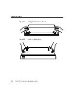
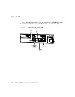
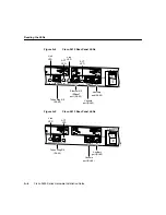
Holding the chassis with both hands, position it as shown in Figure B-1.
Step 5
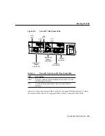
Slide the top section away from the bottom section as shown in Figure B-2.
Warning
Do not touch the power supply when the power cord is connected. For systems
with a power switch, line voltages are present within the power supply even when the
power switch is OFF and the power cord is connected. For systems without a power
switch, line voltages are present within the power supply when the power cord is
connected.
Warning
Before opening the chassis, disconnect the telephone-network cables to avoid
contact with telephone-network voltages.

