


5-45
Cisco ONS 15454 Installation and Operations Guide
November 2001
Chapter 5 SONET Topologies
Linear ADM Configurations
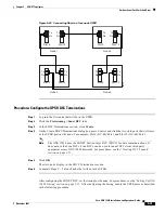
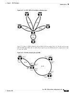
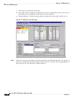
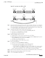
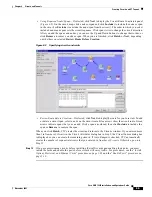
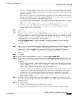
Figure 5-36 Converting a linear ADM to a UPSR
Step 8
Physically reroute the other protect fiber to connect the two end nodes. In the
Figure 5-36
example, the
fiber between Node 1/Slot 5 and Node 2/Slot 5 is rerouted to connect Node 1/Slot 5 to Node 3/Slot 13.
If you are leaving the OC-N cards in place, go to Step 13. If you are removing the cards, complete Steps
9 – 12. (In this example, cards in Node 2/Slots 5 and 13 are removed.)
Step 9
In the middle node, place the cards in Slots 5 and 13 out of service:
a.
Display the first card in card view and select the Provisioning > Line tabs.
b.
Under Status, select Out of Service. Click Apply.
c.
Repeat Steps a and b for the second card.
Step 10
Delete the equipment records for the cards:
a.
Display the node view. (In card view, click the Up arrow on the toolbar.)
b.
Right-click the card you just took out of service (e.g. Slot 5) and select Delete Card. (You can also
go to the Inventory tab, select the card, and click Delete.)
c.
Click Yes on the confirmation dialog box.
d.
Repeat (a) through (c) for the second card (e.g. Slot 13).
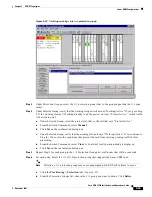
Step 11
Save all circuit information.
a.
In node view, select the Provisioning > Circuits tab.
b.
Record the circuit information using one of the following procedures:
–
From the File menu, select Print to print the circuits table, or,
–
From the File menu, select Export to export the circuit data in HTML, CSV (comma separated
values), or TSV (tab separated values). Click Ok and save the file in a temporary directory.
See the
“Printing and Exporting CTC Data” section on page 2-26
for more information.
Step 12
Remove the OC-N cards that are no longer connected to the end nodes (Slots 5 and 13, in the example).
Step 13
Display one of the end nodes (Node 1 or Node 3 in the example).
Step 14
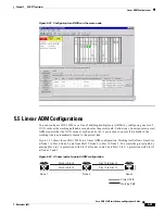
Click the Provisioning > Sonet DCC tabs.
Slot 6 to Slot 6
Linear
ONS 15454
Node 1
Slot 5 to Slot 5
Slot 12 to Slot 12
ONS 15454
Node 2
Slot 13 to Slot 13
ONS 15454
Node 3
Slot 6
(East)
UPSR
ONS 15454
Node 1
ONS 15454
Node 2
ONS 15454
Node 3
Slot 6
(West)
Slot 12
(East)
Slot 12
(West)
Slot 13
(East)
Slot 5
(West)
32135
Содержание 15454-TCC - Network Processor Card
Страница 22: ...Figures xxii Cisco ONS 15454 Installation and Operations Guide November 2001 ...
Страница 32: ...Procedures xxxii Cisco ONS 15454 Installation and Operations Guide November 2001 ...
Страница 158: ...3 20 Cisco ONS 15454 Installation and Operations Guide November 2001 Chapter 3 Node Setup Viewing CTC Software Versions ...
Страница 388: ...11 10 Cisco ONS 15454 Installation and Operations Guide November 2001 Chapter 11 SNMP SNMP Remote Network Monitoring ...


