Maintenance
0 mm
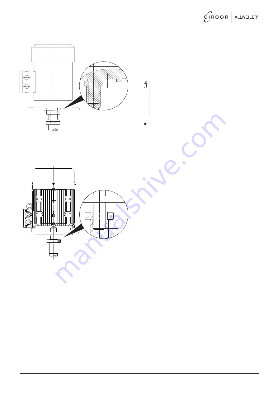
4. For version of the stub shaft with hole diameter up to
55 mm (A) and above 60 mm (C), carefully push on the
motor until the stub shaft rests flush against the shaft collar
of the motor shaft.
–
Ensure that no excessive axial forces are applied to the
pump shaft.
0 mm
5. For the stub shaft version with hole diameter up to 55 mm
and clamping ring (B), carefully push on the motor until the
motor shaft lies flush in the bottom of the stub shaft hole.
–
Ensure that no excessive axial forces are applied to the
pump shaft.
6. Screw in the motor bolts and tighten them.
–
Ensure that the stub shaft continues to rest flush
against the collar of the motor shaft (A, C).
–
Ensure that the motor shaft continues to rest flush in
the base of the stub shaft hole (B).
7. Undo and unscrew the jack screw. Screw in the socket
head cap screw (914.06) and tighten it with a torque wrench
(→ 9.2.4 Tightening torques, Page 40).
8. Install the safety equipment:
–
Guard sheet for the motor bell housing
9. Install the auxiliary devices:
–
Manometer lines and fixtures at the pump
–
Auxiliary pipes
10. Turn the stub shaft by hand:
–
Ensure the stub shaft can be turned easily without pres-
sure points.
7.5
Ordering spare parts
For trouble-free replacement in the event of faults, we rec-
ommend keeping entire slide-in units or spare pumps avail-
able on site.
The application guidelines described in DIN 24296 rec-
ommend provisions for two years of continuous use
(→ 9.3 Spare parts for two years of continuous operation
according to DIN 24296, Page 42).
Have the following information ready to hand when order-
ing spare parts (→ type plate):
–
Pump type
–
Pump number
–
Year of manufacture
–
Part number
–
Designation
–
Quantity
26
NI series
BA-2021.06 en-US
550 113 – 146-900/E


