background image

Setup and connection

5.2.3

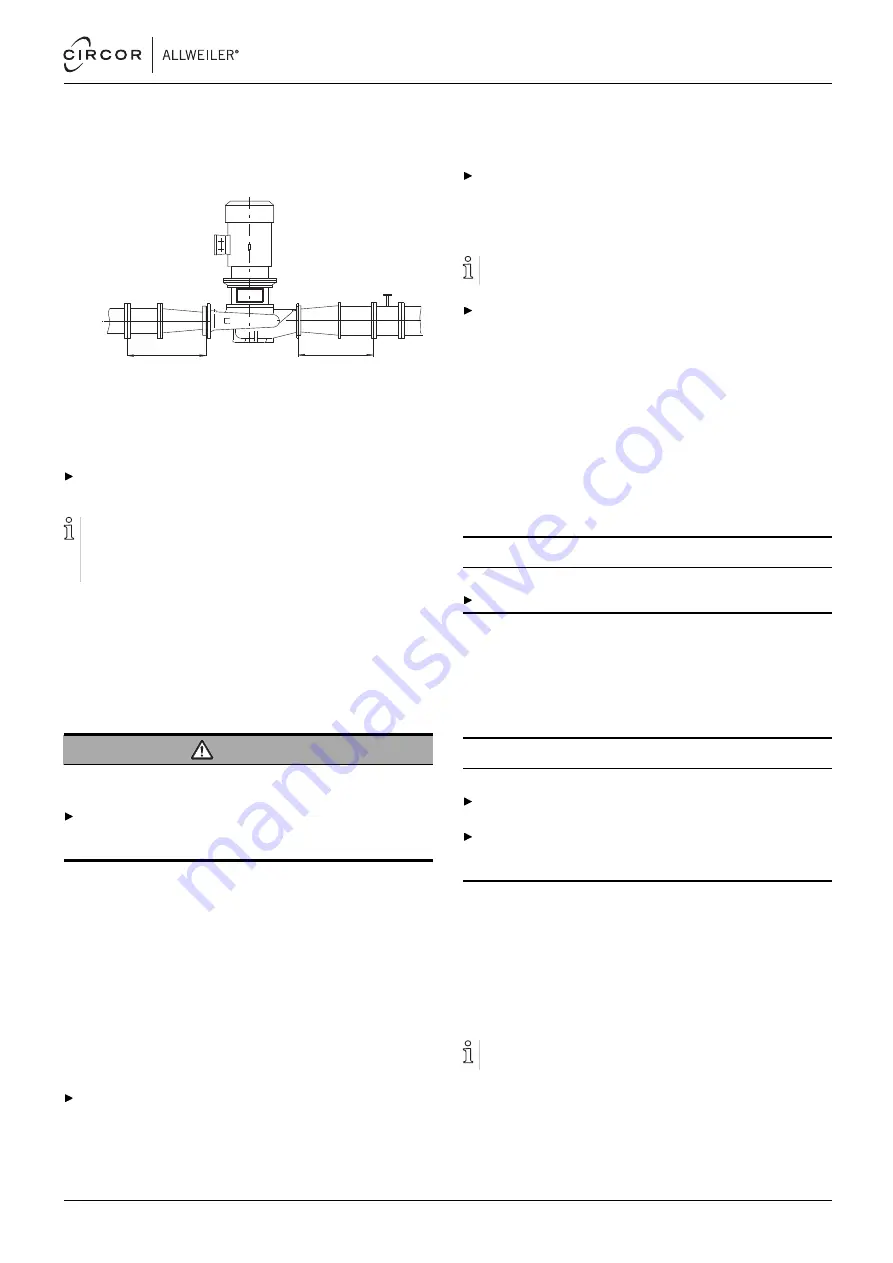
Specifying pipe lengths

A

B

Fig. 8

Straight pipe lengths upstream and downstream
of the pump (recommended)

A > 5 x nominal suction pipe diameter
B > 5 x nominal pressure pipe diameter

Maintain the recommended minimum values when
installing the pump.

Suction side: shorter pipes are possible but may restrict
the hydraulic performance.
Pressure side: shorter pipes are possible but can result in
increased operating noise.

5.2.4

Optimizing cross-section and direction
changes

1. Avoid radii of curvature of less than 1.5 times the nominal

pipe diameter.

2. Avoid abrupt changes of cross-section along the piping.

5.2.5

Discharging leaks

WARNING

Risk of injury and poisoning due to hazardous pumped
liquids!

Safely collect any leaking pumped liquid, then discharge
and dispose of it in accordance with environmental regula-
tions.

1. Provide equipment for collecting and discharging leaking

liquids.

2. Ensure the free discharge of leaking liquids.

5.2.6

Providing safety and control devices
(recommended)

Avoid impurities

1. Integrate a filter in the suction pipe.
2. To monitor impurities, install a differential pressure gauge

with a contact manometer.

Avoid reverse running

Install a non-return valve between the pressure flange and
the gate valve to ensure the medium does not flow back
when the pump is switched off.

Avoid running empty

For suction operation: install a foot valve in the suction pipe
to prevent the pump and suction pipe from running empty
during downtimes.

Make provisions for isolating and shutting off the pipes

For maintenance and repair work.

Provide shut-off devices in the suction and pressure pipes.

Allow measurements of the operating conditions

1. Provide manometers for pressure measurements in the

suction and pressure pipes.

2. Provide load monitors (overload and underload) on the

motor side.

3. Provide for pump-side temperature measurements.

5.3

Installing in the pipe

5.3.1

Keeping the piping clean

NOTE

Material damage due to impurities in the pump!

Make sure no impurities can enter the pump.

1. Clean all piping parts and armatures prior to assembly.
2. Ensure no flange seals protrude inwards.
3. Remove any blind flanges, plugs, protective foils and/or

protective paint from flanges.

5.3.2

Installing the pump unit without feet/base

NOTE

Material damage due to excessive forces!

Make sure the pipe is able to bear the weight of the pump
aggregate and all operating forces which occur.
Make sure that the distance and alignment of the pipe
flanges comply with the pump dimensions (→ setup draw-
ing).

1. Remove the transport and sealing covers from the pump.
2. Lifting the pump unit (→ 4.1 Transport, Page 14).
3. Raise the pump aggregate between the pipe ends.

Observe the pumping direction in the process.

4. Screw the suction flange and pressure flange to the pipe,

complying with the prescribed tightening torques.

5.3.3

Setting up pump unit with feet/base

Pump units with a base are installed vertically (motor at the
top).

1. Lift the pump unit and set it down at the installation location

(→ 4.1 Transport, Page 14).

2. Install the pump unit (→ setup drawing).

550 113 – 146-900/E

BA-2021.06 en-US

NI series

17

Содержание ALLWEILER NI Series

Страница 1: ...US 146 900 E ID No 550 113 ALLWEILER GmbH Postfach 1140 Allweilerstr 1 78301 Radolfzell Germany Phone 49 0 7732 86 0 Fax 49 0 7732 86 436 E mail service allweiler de Internet http www allweiler com W...

Страница 2: ...timizing cross section and direction changes 17 5 2 5 Discharging leaks 17 5 2 6 Providing safety and control devices recommended 17 5 3 Installing in the pipe 17 5 3 1 Keeping the piping clean 17 5 3...

Страница 3: ...levels 39 9 2 4 Tightening torques 40 9 2 5 Cleaning agents 40 9 2 6 Flange loads 41 9 3 Spare parts for two years of continuous operation according to DIN 24296 42 9 4 Declaration of harmlessness 43...

Страница 4: ...anced mechanical seal sizes with diameter 40 at the shaft seal 37 Fig 22 Version with intermediate ring for sizes 65 400 38 Fig 23 Version with housing cover 470 315 sizes 65 315 80 315 and 100 315 38...

Страница 5: ...s especially all safety instructions and warnings Tab 1 Target groups and their duties 1 2 Other applicable documents Document Purpose ATEX additional instructions Operation in explosion hazard areas...

Страница 6: ...ces of disregarding them Symbol Meaning Safety warning sign Take note of all information highlighted by the safety warning sign and follow the instructions to avoid injury or death Instruction 1 2 Mul...

Страница 7: ...g water Use of the pump for foodstuffs or drinking water must be speci ed in the order data sheet Only select the setup type according to this operating man ual For example the following are not allow...

Страница 8: ...le for drives of screw pumps When using combustion engines consult Allweiler For pumps with stub shaft connect drive system and pump directly with stub shaft Use elastic coupling according to DIN 740...

Страница 9: ...liquid and dispose of it in accordance with the environmental rules and require ments Drain the pump when carrying out maintenance and repair work Use protective equipment when carrying out any work...

Страница 10: ...Density 8 Kinematic viscosity 9 Reference to ATEX additional instructions 10 Explosion protection mark 11 Power consumption 12 Motor speed 13 Differential head 14 Flow rate 15 Pump type code 3 1 2 Di...

Страница 11: ...Size standard nominal diameter 3 Nominal impeller diameter 4 Hydraulic number 5 Actual impeller diameter mm 6 Shaft seal 7 Mounting type optional 8 Material key 9 Stub shaft bore hole diameter mm 10 O...

Страница 12: ...shaft 4 Limit for heat insulation 5 Impeller 6 Volute casing 7 Shaft seal 8 Guard sheet 3 3 Shaft seals Only one of the following shaft seals can be used 3 3 1 Mechanical seals Mechanical seals have...

Страница 13: ...on 3 Quench space The pressure of the pumped uid is higher than the pressure of the quench medium during quenching The gasket surfaces are lubricated by the pumped uid Application examples Pumped medi...

Страница 14: ...for non rusting materials Contact the manufacturer for recommendations regarding preservatives NOTE Material damage due to inappropriate treatment for stor age Treat the pump properly inside and outsi...

Страница 15: ...regu lations 3 For storage times in excess of 6 months Replace the elastomer parts made of EP rubber EPDM Check all elastomer parts O rings shaft seals for proper elasticity and replace them if neces...

Страница 16: ...ary to maintain the temperature of the pumped medium NOTE Material damage on the bearing or shaft seal due to over heating Only install the heat insulation on the volute casing Fig 5 Layout Page 12 In...

Страница 17: ...nning empty during downtimes Make provisions for isolating and shutting off the pipes For maintenance and repair work Provide shut off devices in the suction and pressure pipes Allow measurements of t...

Страница 18: ...diameter up to 55 mm B Version for stub shaft hole diameter up to 55 mm and clamping ring C Version for stub shaft hole diameter starting from 60 mm 1 Cheese head screw 2 Stub shaft 3 Shaft key groov...

Страница 19: ...est ush in the base of the stub shaft hole B 12 Undo and unscrew the jack screw Screw in the socket head cap screw 914 06 and tighten it with a torque wrench 9 2 4 Tightening torques Page 40 13 Instal...

Страница 20: ...sealing system are met 5 Ensure that the permissible container pressure is not exceeded on blocking pressure systems manufac turer s speci cations 6 1 4 Filling and bleeding Auxiliary systems ready f...

Страница 21: ...ture check that the pump is not leaking 6 2 2 Switching off Pressure side armature closed recommended 1 Switch off the motor 2 Check all connecting bolts and tighten them if necessary 6 3 Shutting dow...

Страница 22: ...Replace antifriction bearings Tab 9 Measures to be taken after prolonged shutdown periods 2 Carry out the same steps as for the initial start up 6 2 Start up Page 21 6 5 Operating the stand by pump St...

Страница 23: ...service life cannot be made 7 2 1 Mechanical seals Mechanical seals have functional leaks manufacturer s speci cations Single mechanical seals with quenching any drastic rise in the level of the quenc...

Страница 24: ...t down depressurized and emptied Manometer lines manometer and xtures dismounted Safety guarding removed In production the pumps are constructed to a standard process The slide in unit can be removed...

Страница 25: ...ne spare parts Replace seals inserting them so that they cannot rotate Adhere to the prescribed tightening torques 9 2 4 Tightening torques Page 40 2 Clean all parts 9 2 5 Cleaning agents Page 40 Do n...

Страница 26: ...do and unscrew the jack screw Screw in the socket head cap screw 914 06 and tighten it with a torque wrench 9 2 4 Tightening torques Page 40 8 Install the safety equipment Guard sheet for the motor be...

Страница 27: ...r suction strainer blocked or encrusted Clean the supply suction pipe pump or suction strainer X X X Supply suction pipe cross section too narrow Increase the cross section Remove any encrustations fr...

Страница 28: ...e impeller diameter X X X Geodetic differential head pipe ow resistances and or other resistances lower than speci ed Throttle down the ow rate at the pressure side armature Observe the minimum ow rat...

Страница 29: ...cal seal worn Replace the mechanical seal X Housing seal defective Replace the housing seal X Shaft sleeve is in ltrated Replace the shaft sleeve and or O ring X X X Pump distorted Check the pipe conn...

Страница 30: ...07 Seal ring 412 01 O ring 433 01 Mechanical seal 502 01 Wear ring 509 01 Intermediate ring 509 02 Intermediate ring 510 01 Spacer ring Part no Designation 514 01 Threaded ring 515 01 Clamping ring 52...

Страница 31: ...plate digital nameplate 971 01 Type plate Tab 14 Designations of components according to part numbers 9 1 3 Sectional drawings Fig 12 U3 D Unbalanced mechanical seal sizes with diameter 16 at the shaf...

Страница 32: ...Appendix 220 01 515 01 914 06 Fig 13 Stub shaft version with clamping ring 32 NI series BA 2021 06 en US 550 113 146 900 E...

Страница 33: ...Appendix Fig 14 U3 D Unbalanced mechanical seal sizes with diameter 30 at the shaft seal optional optional from motor size 225 mandatory 550 113 146 900 E BA 2021 06 en US NI series 33...

Страница 34: ...ft diameter 24 at the shaft seal 686 01 Fig 16 Attachment of the guard sheet to the motor bell housing 901 01 161 01 901 02 400 02 Fig 17 Version with housing cover 360 250 sizes 40 250 50 250 and 65...

Страница 35: ...Appendix Fig 18 Two stage sizes with diameter 30 at the shaft seal non cooled unbalanced mechanical seal optional optional from motor size 225 mandatory 550 113 146 900 E BA 2021 06 en US NI series 35...

Страница 36: ...x 220 01 515 01 914 06 Fig 19 Stub shaft version with clamping ring 920 02 902 02 901 02 400 02 161 01 Fig 20 Housing cover version sizes 2 40 250 and 2 50 250 36 NI series BA 2021 06 en US 550 113 14...

Страница 37: ...Appendix Fig 21 U3 D Unbalanced mechanical seal sizes with diameter 40 at the shaft seal optional 550 113 146 900 E BA 2021 06 en US NI series 37...

Страница 38: ...with intermediate ring for sizes 65 400 901 01 161 01 901 02 400 02 Fig 23 Version with housing cover 470 315 sizes 65 315 80 315 and 100 315 686 01 Fig 24 Attachment of the guard sheet to the motor b...

Страница 39: ...re C Long term Short term Setup height above sea level m 20 to 40 85 100 1000 Tab 16 Ambient conditions 9 2 3 Sound pressure levels Measuring conditions Distance to the pump 1 m Operation cavitation f...

Страница 40: ...15 30 904 05 M8 A4 12 914 06 M8 M10 12 9 25 50 914 10 M16 M10 8 8 167 922 01 M12 x 1 5 M16 x 1 5 M20 x 1 5 M24 x 1 5 1 4404 20 45 96 157 Tab 18 Tightening torques 9 2 5 Cleaning agents Application ar...

Страница 41: ...66 450 300 350 644 32 450 525 425 812 550 375 425 790 40 550 625 500 971 650 450 525 949 50 750 825 675 1303 700 500 575 1035 65 925 1050 850 1637 750 550 600 1107 80 1125 1250 1025 1969 800 575 650 1...

Страница 42: ...ng ring Socket head cap screw Impeller nut Spring ring Shaft key 1 1 1 2 2 2 3 30 230 01 Impeller all single stage pump sizes 1 1 1 2 2 3 30 230 02 230 03 514 01 904 05 Impeller rst stage Impeller sec...

Страница 43: ...ata sheet if applicable to service emea gr circor com Please understand that return shipments without a declaration of harmlessness cannot be processed until such declaration is received Pump type Ser...

Страница 44: ...he operating instructions are observed complies with the following applicable EC directives Machine Directive 2006 42 EC The protection targets of the low voltage directive 2006 95 EC valid until 19 A...

Отзывы: