Setup and connection
5
Setup and connection
For pumps in explosion hazard areas (→ ATEX additional
instructions).
NOTE
Material damage due to distortion or passage of electrical
current in the bearing!
Do not make any structural modifications to the pump unit
or pump casing.
Do not carry out any welding work on the pump unit or
pump casing.
NOTE
Material damage caused by dirt!
Do not remove the transport seals until immediately before
setting up the pump.
Do not remove any covers or transport and sealing covers
until immediately before connecting the pipes to the pump.
5.1
Preparing the setup
5.1.1
Checking the ambient conditions
Make sure the required ambient conditions are fulfilled
(→ 9.2.2 Ambient conditions, Page 39).
5.1.2
Preparing the installation site
Ensure the installation site meets the following conditions:
–
Pump is freely accessible from all sides
–
Sufficient space for installation/removal of the pipes
and for maintenance and repair work, especially for the
removal and installation of the pump and the motor
–
Pump not exposed to external vibrations (damage to
bearings)
–
Frost protection
5.1.3
Removing the preservative
If the pump is to be put into operation immediately after
setup and connection:
–
Remove
the
preservative
prior
to
installation
(→ 4.4 Removing the preservative, Page 15).
5.1.4
Installing the heat insulation (optional)
Only necessary to maintain the temperature of the pumped
medium
NOTE
Material damage on the bearing or shaft seal due to over-
heating!
Only install the heat insulation on the volute casing (→ Fig.
5 Layout, Page 12).
Install the heat insulation properly.
5.1.5
Checking the guard sheet alignment
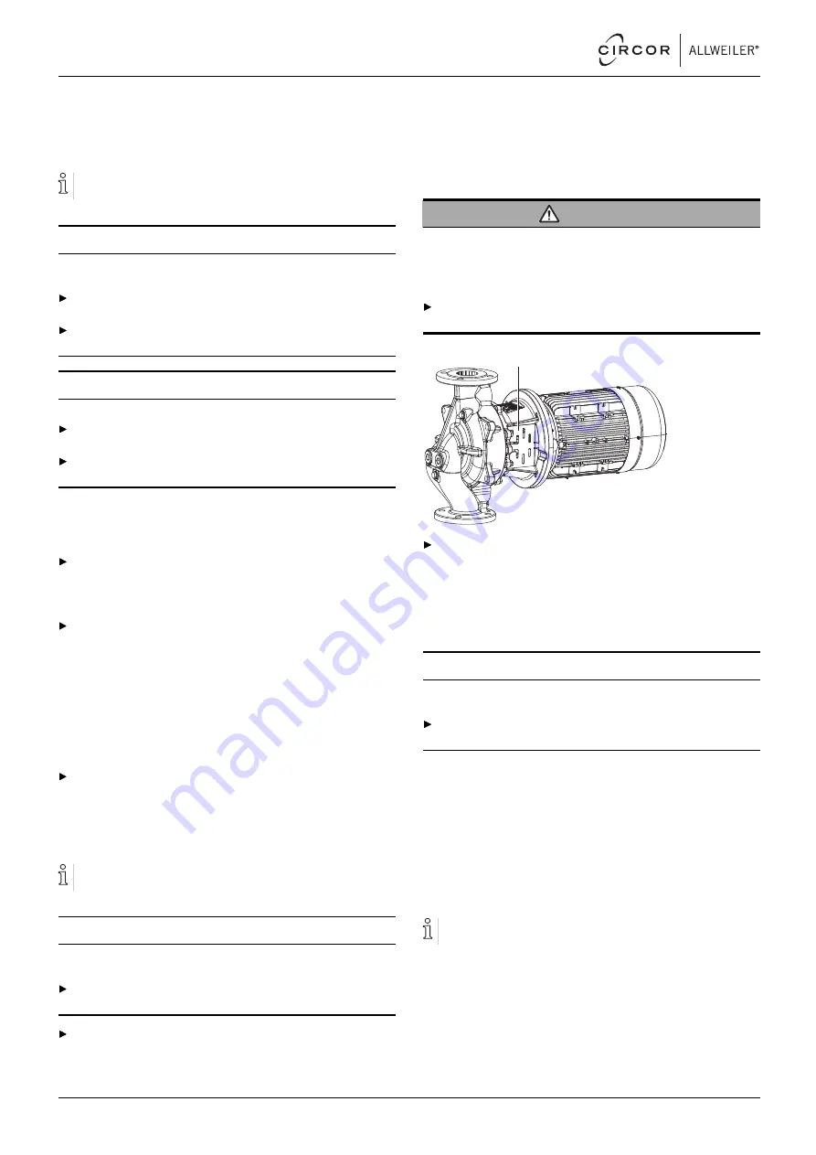
WARNING
Risk of explosion due to incorrect guard sheet alignment!
Heavy falling objects can deform the guard sheet and hit rotat-
ing parts. The flying sparks can ignite an explosive atmos-
phere.
For horizontal installation position: Install the pump with
guard sheets aligned vertically.
1
For horizontal installation position, ensure that the guard
sheets (1) are aligned vertically.
5.2
Planning the pipes
5.2.1
Specifying supports and flange connections
NOTE
Material damage due to excessive forces and torques
exerted by the piping on the pump!
Do not exceed the permissible limits (→ 9.2.6 Flange
loads, Page 41).
1. Calculate the pipe forces, taking every possible operating
condition into account:
–
Cold/warm
–
Empty/full
–
Unpressurized/pressurized
–
Shift in position of flanges
2. Ensure the pipe supports have permanent low-friction
properties and do not seize up due to corrosion.
5.2.2
Specifying nominal diameters
Keep the flow resistance in the pipes as low as possible.
1. Make sure the nominal suction pipe diameter is, as far as
possible, ≥ to the nominal suction flange diameter.
–
Recommended flow rate speed < 1 m/s
2. Make sure the nominal pressure pipe diameter is ≥ as pos-
sible to the nominal outlet flange diameter.
–
Recommended flow rate speed < 3 m/s
16
NI series
BA-2021.06 en-US
550 113 – 146-900/E


