Total Solution for Industrial Automation
16
CH 4. Functions
4.3
Controlling duty cycle (PWM) (Buffer Memory Offset 10 ~ 21)
The PWM provides functions to control the duty cycle from 0.0% to 100.0% with a
1/1000 resolution. Duty cycles can be controlled by a channel, for a maximum of 12
channels. Duty cycle can be set by using TO instruction at OFFSET 10~21 area of
buffer memory. For more information, please refer to Section 3.2.
When using TO instruction on the buffer memory, the output terminal will be
configured to set the duty cycle and being output. To prevent the drastic changes in
the duty cycle, please refer to the section on ramp control (Sec 4.4).
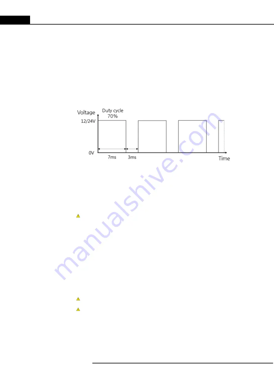
[Figure 7] Example of duty cycle control (PWM)
If 70.0% of duty cycle is set for a digital signal of 12V/24V voltage, an average
output of 8.4V/16.8V will be available. Duty cycle control(PWM) can be utilized in
various way to substitute analog signal. For example, the velocity of motor or the
ratio of valve opening (open/closed) can be configured.
Please note that if the value of the duty cycle is set to be greater than 100.0%, it
will be recognized as a 100.0%.
4.4
Ramp control
Ramp control serves the purpose of preventing drastic changes in the pulse
frequency and duty cycle. If ramp control is enabled (non-zero control time), the
output changes gradually. If it is disabled (control time is set to zero), output signals
change immediately, without any processing.
Please be advised that:
Ramp control time should be entered prior to the value for intended purposes.
In case of power reset or CPU STOP during ramp operation, enter the value again
by using TO instruction as all set value of buffer memory will be set back to initial
value(0).


