


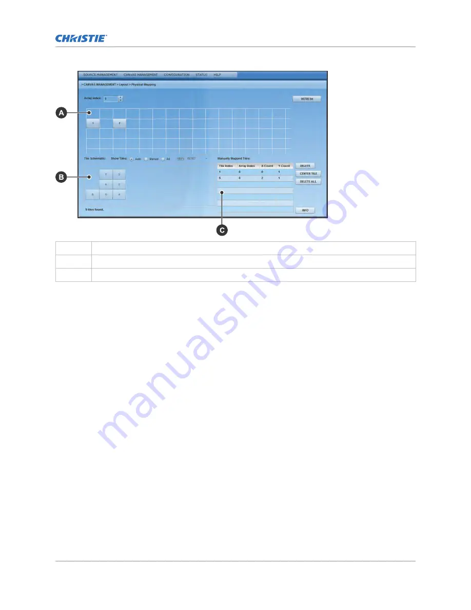
A
Main grid
B
Physical layout or map of all tiles
C
Manually mapped tiles
1. Ensure Automatic Array Configuration is enabled (on page 32).
2. Select Canvas Management > Layout > Physical Mapping.
3. In the Tile Schematic section click a tile.
4. Drag and drop the tile into the main grid to manually map it.
5. To center the main grid on the currently selected manually mapped tile, click Center Tile.
For example, if you want to manually map a tile to location x=20 and y=20, select a manual
mapping from the table and click Center Tile to make the main grid reposition the tile to the
center of the main grid.
6. To bring up the properties of each tile, click Info.
Use the tile system information screen to see the number of each tile.
Viewing the array as a wire map
Display the wiring of the ECU and tiles as text. Use the wire map to verify the cabling between the
ECU and the tiles, and to diagnose issues with the array.
1. Select Canvas Management > Diagnostics and Calibration > Wire Map.
2. Read the wire map.
The left column identifies the coordinates of the output tile and, and the right column is the
input tile.
3. To save the wire map as a .cvs file, click Export.
Configuring the array
Christie MicroTiles Installation and Setup Guide
35
020-100329-15 Rev. 1 (05-2018)
Copyright
©
2018 Christie Digital Systems USA, Inc. All rights reserved.
Содержание MicroTiles
Страница 1: ...Installation and Setup Guide 020 100329 15 Christie MicroTiles ...
Страница 43: ......


