Section 3: Operation
020-100001-01 Rev. 01 (04/07)
3-59
.
To return to the factory-set color primaries, such as when a projector is moved to
different site, you must access the
Service
menu (password-protected). Select the
“
Reset to Factory Defaults?”
option in the
Color Primaries
submenu. Then repeat the
calibration process describe above, if desired, and continue with matching of colors.
Color Adjustment Procedure
Once the
Color Primary Settings
are calibrated for the site (see above), use the
Color
Adjustments by X,Y
or
Color Saturation
menu to further refine each projector’s
fundamental colors so that the hue and intensity of each color appears the same from
one display to another. Once matched, you will have created a single new shared
range of colors or “color gamut” that all of your projectors can produce. This
palette—named User 1, 2, 3 or 4—can be applied or disabled for a source at any time
throughout a bank of adjacent displays, simplifying both the setup and maintenance of
a “seamless” wall.
1.
Set up and optimize all projector settings. You can ignore color temperature, since
you will be redefining color performance in this procedure, but do optimize each
projector in every other aspect. Closely align all screen edges.
2.
Assign projector numbers to make communications easier. Use desired keypad.
3.
Use the same lamp mode for all projectors, and do the following:
•
Set
Select Color Adjustment
to “Max Drives”
•
Display a full white test pattern
•
Adjust lamp power and Optical Aperture until adjacent white fields appear the
same brightness.
4.
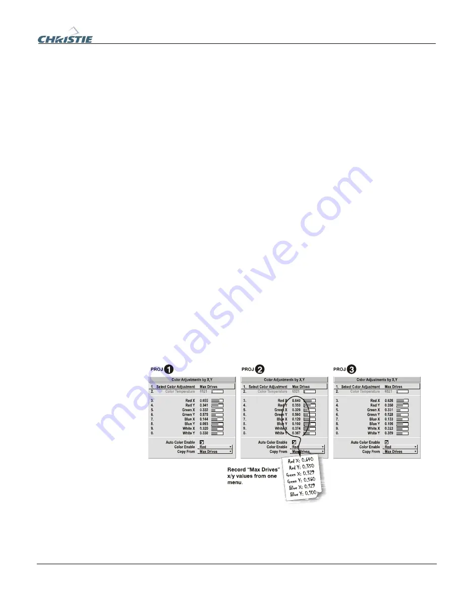
Display the
Color Adjustments by X,Y
menus for all projectors. Each menu shows
the x/y coordinates defining the “Max Drives” color gamut for this projector. Note
the values shown in one (any) of the displays. See Figure 3.13. Or use the “Copy
From” function to copy them into a “User” gamut in one projector.
Figure 3.13. Jot Down a Set of ”Max Drives” X/Y Values
5.
In each projector, select a “User” color adjustment (1-4) to enable
Color
Adjustments by X,Y
changes. Then enter your recorded x/y values into each menu
(Figure 3.14).
Содержание DW6Kc
Страница 1: ...U s e r s M a n u a l U s e r s M a n u a l 020 100001 01 ...
Страница 3: ......
Страница 5: ......
Страница 9: ......
Страница 16: ...Section 2 Installation and Setup 020 100001 01 Rev 01 04 07 2 7 Figure 2 1 Vertical Offset Examples ...
Страница 17: ...Section 2 Installation and Setup 2 8 020 100001 01 Rev 01 04 07 Figure 2 2 Lens Vertical Offsets ...
Страница 19: ...Section 2 Installation and Setup 2 10 020 100001 01 Rev 01 04 07 Figure 2 4 Lens Horizontal Offsets ...
Страница 103: ......
Страница 119: ......
Страница 127: ......
Страница 135: ......
Страница 137: ......
Страница 139: ......
Страница 141: ...Appendix D Throw Distance D 2 020 100001 01 Rev 01 04 07 SXGA Lenses f ...
Страница 142: ...Appendix D Throw Distance 020 100001 01 Rev 01 04 07 D 3 ...
Страница 143: ...Appendix D Throw Distance D 4 020 100001 01 Rev 01 04 07 ...
Страница 144: ...Appendix D Throw Distance 020 100001 01 Rev 01 04 07 D 5 ...
Страница 145: ...Appendix D Throw Distance D 6 020 100001 01 Rev 01 04 07 ...
Страница 146: ...Appendix D Throw Distance 020 100001 01 Rev 01 04 07 D 7 ...
Страница 147: ...Appendix D Throw Distance D 8 020 100001 01 Rev 01 04 07 ...
Страница 148: ...Appendix D Throw Distance 020 100001 01 Rev 01 04 07 D 9 ...
Страница 149: ...Appendix D Throw Distance D 10 020 100001 01 Rev 01 04 07 ...
Страница 173: ......


