Section 3: Operation
User’s Manual 3-65
.
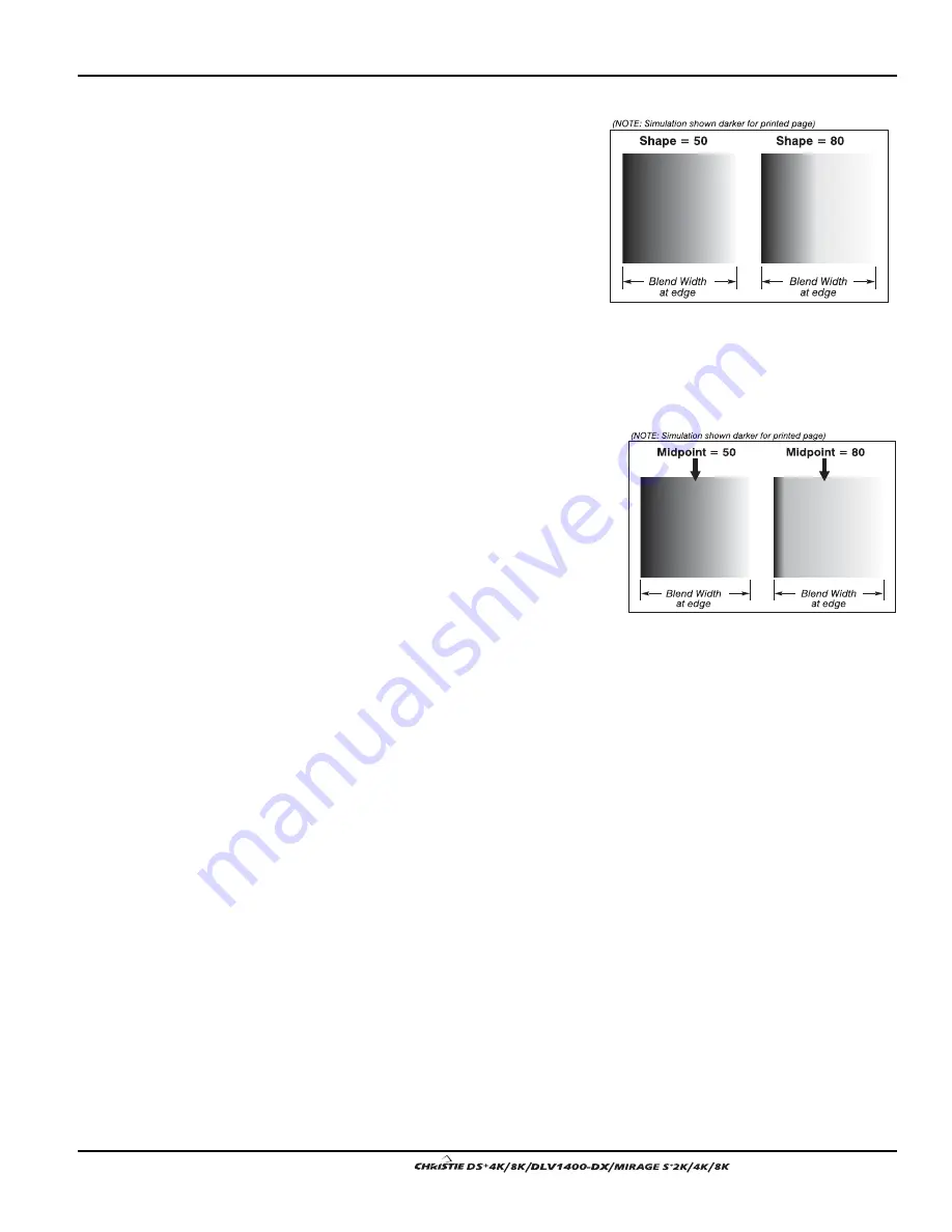
Blend Shape
determines the rate
of roll-off across the blend width,
i.e. how quickly the white levels
across the blend change from
light and dark. Increasing the
Blend Shape setting accelerates
the rate of change at both
extremes so that less of the region
appears mid-gray (see Figure
3.37). Decreasing the Blend
Shape setting slows the rate of
change so that more of the region
appears mid-gray. For most
applications, this subtle control is
best left close to 50.
Blend Midpoint
determines the white
level at the blend midpoint (the point
equidistant between the beginning
and end of the blend). Increasing the
Blend Midpoint setting creates a
blend that appears brighter than the
rest of the image. Decreasing the
Blend Midpoint setting creates a
blend that is darker than the rest of
the image. A setting of 50 means the
midpoint is approximately 50%
black—for best results in most
applications, keep fairly close to this default.
Other Functions
For convenience, the Edge Blending submenu also includes related options for
enabling a specific color and/or test pattern, or for working with colors or the lamp.
Such functions duplicate those provided elsewhere in the menu system.
Edge Blending Procedure
NOTE: Before attempting to work with edge blending software functions, you must 1)
physically align the projectors/images by correctly overlapping the displays from your
intended external source, and 2) Match colors and Brightness Uniformity.
IMPORTANT
For a shared edge, all
Blend
procedures and settings
should be identical on BOTH projectors.
1. Start with 2 projectors. Display full white field test pattern from both.
2. In the Edge Blending submenu, enable Edge Blending by entering a checkmark in
the top checkbox.
3.
SET STARTING POINTS FOR ADJUSTMENT
:
Set all blend widths to 0.
Go to “More” and set everything in the Edge Blending (2) menu to 50.
Figure 3.37. “Shape” Examples
Figure 3.38. “Midpoint” Examples
Содержание DS+4K
Страница 2: ......
Страница 11: ...Section 2 Installation and Setup User s Manual 2 7 Figure 2 2 Vertical Offset Examples...
Страница 12: ...Section 2 Installation and Setup 2 8 User s Manual Figure 2 3 Lens Vertical Offsets...
Страница 14: ...Section 2 Installation and Setup 2 10 User s Manual Figure 2 5 Lens Horizontal Offsets...
Страница 22: ......
Страница 75: ...Section 3 Operation User s Manual 3 53 Figure 3 29 Customizing the Input Signal...
Страница 92: ......
Страница 102: ...Section 4 Maintenance 4 10 User s Manual Figure 4 8...
Страница 106: ......
Страница 120: ......
Страница 122: ......
Страница 124: ...Appendix C Serial Communication Cables C 2 User s Manual...
Страница 126: ...Appendix D Throw Distance D 2 User s Manual...
Страница 127: ...Appendix D Throw Distance User s Manual D 3...
Страница 128: ...Appendix D Throw Distance D 4 User s Manual...
Страница 129: ...Appendix D Throw Distance User s Manual D 5...
Страница 130: ...Appendix D Throw Distance D 6 User s Manual...
Страница 131: ...Appendix D Throw Distance User s Manual D 7...
Страница 132: ...Appendix D Throw Distance D 8 User s Manual...
Страница 133: ...Appendix D Throw Distance User s Manual D 9...
Страница 134: ...Appendix D Throw Distance D 10 User s Manual...


