Section 3: Operation
3-36
User’s Manual
Settings in the Communications
submenu define and control how
single or multiple projectors are
can link with each other and with a
controlling device.
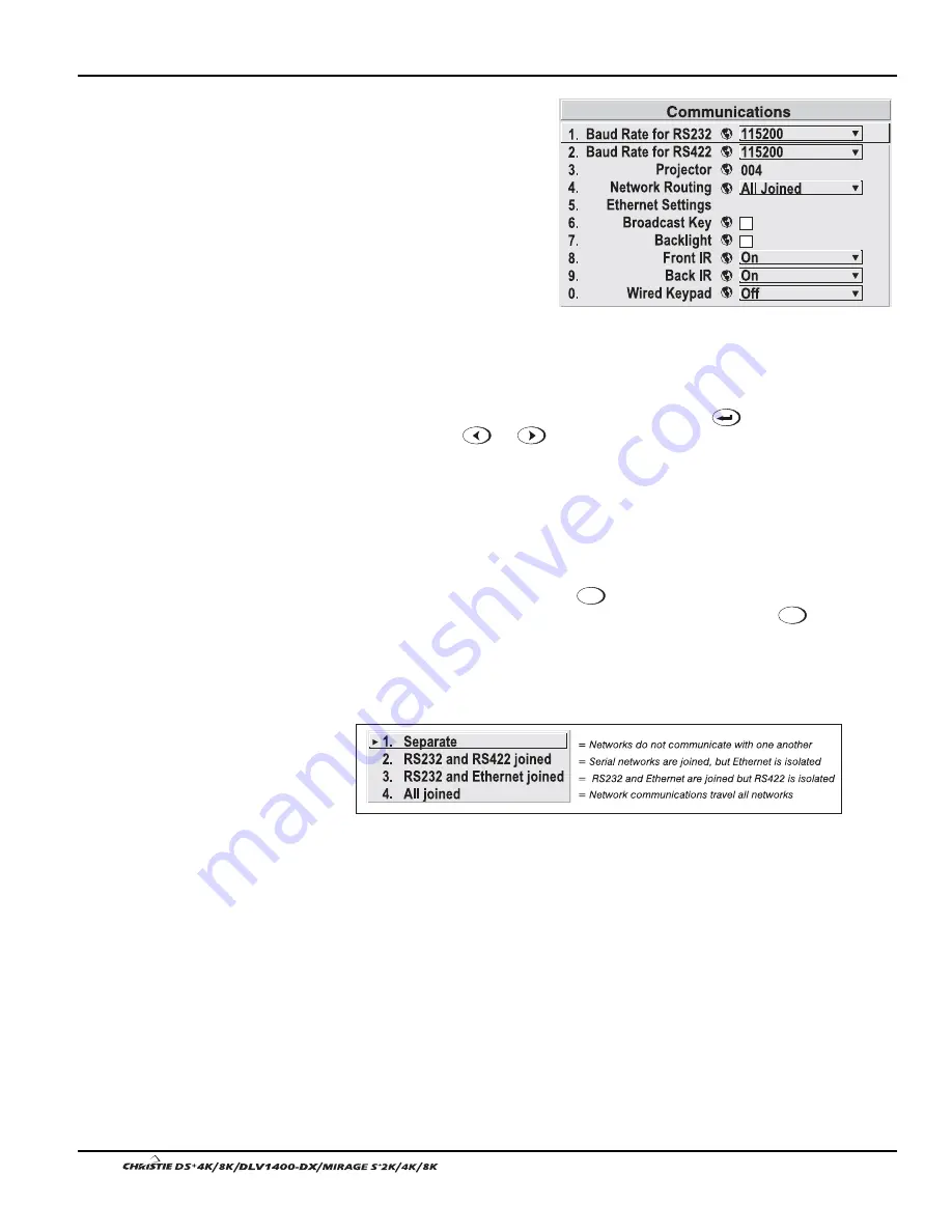
Baud Rates
The baud rate setting determines
the speed of communication to and
from the projector on the RS232 or
RS422 links. The maximum rate
for either standard is 115200. Set
the baud rate to match that of your
controlling device, such as your PC. If you are unsure about what baud rate to choose,
refer to the documentation for the controlling device. In an existing network of
projectors, if you discover that a projector has a different baud rate, make sure to use
the pull-down list and select the correct baud rate using the
key—do not just
scroll this control with
or
keys. Serial communication is always 8 data bits,
no parity.
Projector
Enter a three-digit number (such as "001”) to assign or change a number to the
projector currently in use. If the current projector already has a number assigned, that
number will appear here (for example, “004” in Figure 3.14, above). Numerical
identity for projectors enables you to communicate with a single projector within a
multiple-projector application (see also
Proj
key in 3.2, Using the Keypads). If you
make a mistake in assigning or changing the projector number, press
Exit
to cancel.
Network Routing
NOTES: 1) Not applicable for stand-alone projectors or simple serial networks with
only one type of controller and linking.
SEPARATE:
Select “Separate” (factory default) to keep RS232, RS422 and Ethernet
messages on their respective paths instead of being broadcast to the other types of
ports. In Figure 3.15A, RS422 controls only the projector to which it is connected. In
Figure 3.15B, either RS232 or RS422 will control the network.
Figure 3.14. Communications
System
Configuration
'
— COMMUNICATIONS —
Содержание DS+4K
Страница 2: ......
Страница 11: ...Section 2 Installation and Setup User s Manual 2 7 Figure 2 2 Vertical Offset Examples...
Страница 12: ...Section 2 Installation and Setup 2 8 User s Manual Figure 2 3 Lens Vertical Offsets...
Страница 14: ...Section 2 Installation and Setup 2 10 User s Manual Figure 2 5 Lens Horizontal Offsets...
Страница 22: ......
Страница 75: ...Section 3 Operation User s Manual 3 53 Figure 3 29 Customizing the Input Signal...
Страница 92: ......
Страница 102: ...Section 4 Maintenance 4 10 User s Manual Figure 4 8...
Страница 106: ......
Страница 120: ......
Страница 122: ......
Страница 124: ...Appendix C Serial Communication Cables C 2 User s Manual...
Страница 126: ...Appendix D Throw Distance D 2 User s Manual...
Страница 127: ...Appendix D Throw Distance User s Manual D 3...
Страница 128: ...Appendix D Throw Distance D 4 User s Manual...
Страница 129: ...Appendix D Throw Distance User s Manual D 5...
Страница 130: ...Appendix D Throw Distance D 6 User s Manual...
Страница 131: ...Appendix D Throw Distance User s Manual D 7...
Страница 132: ...Appendix D Throw Distance D 8 User s Manual...
Страница 133: ...Appendix D Throw Distance User s Manual D 9...
Страница 134: ...Appendix D Throw Distance D 10 User s Manual...


