background image

Section 3: Operation 


 User’s Manual     3-33

.


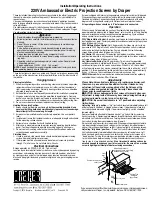
3D STEREO SYNC SELECT 

— 

Define which of the Mirage 3D Stereo Sync Cables 

input connecters is routed to your server. Input A = BNC connector, Input B = 3-pin 
mini-DIN connector. Use only if the cable is present. NOTE: Regardless of which 
input is connected, the output routes to both outputs.


NOTE: See 3.9, 3D Images for a full explanation of 3D Stereo Sync Select use. 

3D STEREO SYNC DELAY

 — 

Set when the L/R frames begin, defining the best 

reference point for synchronizing the display with your glasses. Proper adjustment of 
this delay should eliminate cross-talk and odd colors caused by timing differences 
between the glasses and the projected display. Use this slidebar only if the Mirage 3D 
Stereo Sync Cable
 is connected between the projector’s GPIO port and a server. 
Slidebar values indicate the number of lines that are delayed. 


NOTE: See 3.9, 3D Images for a full explanation of 3D Stereo Sync Delay use. 
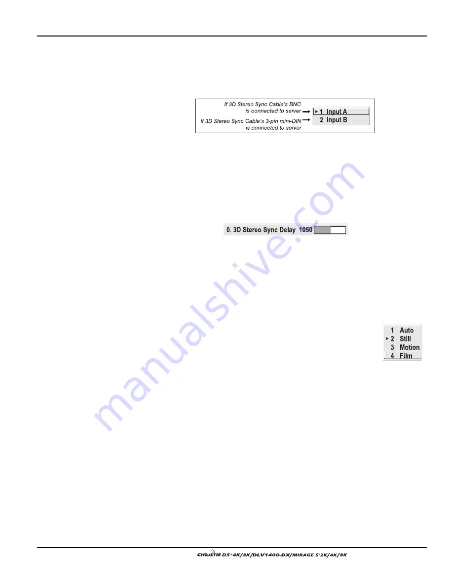
MOTION FILTER

 — 

This control is most useful for smoothing out moving images from 

interlaced sources. In most cases the proper Motion Filter setting is automatically 
determined according to the type of incoming source signal. However, if your source 
is jittery and/or tearing you may wish to “force” a setting to ensure stable processing 
for this source—if desired, override the default “Auto” setting by selecting the 
appropriate motion filter: 

1. 

AUTO:


The projector will automatically use the correct motion 

filter according to the incoming signal. 

2. 

STILL:


For static images with no motion, such as graphics from 

a CD. 

3. 

MOTION:

 For video images that did not originate from film, or 

for moving computer-generated images. 

4. 

FILM:


For video images that originated from film. This will optimize image 

quality and stability. 


FILM MODE THRESHOLD

 —  

This setting determines how sensitively the projector can 

detect if an incoming video signal originated from film or not. 

DETAIL THRESHOLD

 — 

Use “Detail Threshold” to define at what frequency level the 

“Detail” control will begin to magnify high frequencies, which adds details back into 
the image. Raise the threshold to ignore more of these high frequencies, and lower the 
threshold to magnify more of these frequencies. A setting of “0”, for example, means 
no noise will be ignored and all will be magnified. An ideal detail threshold is one in 
which high frequencies that are causing objectionable noise are not magnified when 
using “Detail”, but frequencies which can help sharpen an overly-soft image are 
magnified when using “Detail”. 


Содержание DS+4K

Страница 1: ...19 3 6 Adjusting System Parameters and Advanced Controls 3 34 3 7 Working with the Lamp 3 44 3 8 Status Menu 3 47 3 9 3D Images Mirage Only 3 48 3 10 Using Multiple Projectors 3 57 3 11 Remote Contro...

Страница 2: ......

Страница 3: ...nsional graphic images for simulation virtual reality and other stereographic related applications The DLV1400 DX is designed for the demands of 24 7 control room applications and provides long term r...

Страница 4: ...rojector is under warranty or the warranty has expired Christie s highly trained and extensive factory and dealer service network is always available to quickly diagnose and correct projector malfunct...

Страница 5: ...eneral the further back the projector is positioned from the screen the larger the image will be If required you can level the projector by adjusting its three feet With the projector positioned perpe...

Страница 6: ...rated line cord Turn the Projector ON Press the POWER button on either the remote or built in keypad to turn the projector on Wait a few minutes to allow the projector to warm up The LED status window...

Страница 7: ...Requires separate room Installation cost is usually higher Rear Screen Inverted Mount ceiling Installation ADVANTAGES CONSIDERATIONS Projector is completely hidden Usually good ambient light rejection...

Страница 8: ...the screen This reduces it in other areas A viewing cone similar to that of a curved front screen installation is created This type of screen is better suited for brightly lit rooms where the audienc...

Страница 9: ...brightness use a screen size appropriate for the venue but not larger than required Installing a large screen in a small room is similar to watching television at a close range too large a screen can...

Страница 10: ...offset can also be expressed as the percent of half the image height OR the number of pixels of shift from lens center Refer to Figure 2 2 for some illustrated examples of vertical offset Table 2 1 a...

Страница 11: ...Section 2 Installation and Setup User s Manual 2 7 Figure 2 2 Vertical Offset Examples...

Страница 12: ...Section 2 Installation and Setup 2 8 User s Manual Figure 2 3 Lens Vertical Offsets...

Страница 13: ...y been vertically offset Horizontal offset can also be expressed as the percent of half the image width the number of pixels of shift to one side of lens center Refer to Figure 2 4 for some illustrate...

Страница 14: ...Section 2 Installation and Setup 2 10 User s Manual Figure 2 5 Lens Horizontal Offsets...

Страница 15: ...lain view or have a limited amount of space for projector and audience Available 2005 Use only the CHRISTIE approved ceiling mount kit designed for your projector SPECIAL MOUNTING The projector can be...

Страница 16: ...connections INPUT 1consists of 5 BNCs connectors for linking to a variety of sources The typical connection would be to an RGB source such as a PC Mac DEC Sun SGI and others This projector supports m...

Страница 17: ...o INPUT 1 use the red green and blue BNCs as described in YPbPr Signals below Connect a YPbPr signal component video to INPUT 1 or INPUT 2 as shown in Figure 2 9 NOTES 1 If for some reason the project...

Страница 18: ...high quality DVD players satellite receiver and digital cable TVs NOTE 1 To ensure true digital output from devices that transmit digital signals connect to the DVI I connector 2 DVI loop through is...

Страница 19: ...connectors not both and control the projector remotely by entering specific serial communication commands Connecting RS 232 The two 9 pin DIN connectors labeled RS232 IN and RS232 OUT on the input pa...

Страница 20: ...ur projector Figure 2 13 Connecting RS422 Ethernet Communications To add the projector to an existing Ethernet network with other equipment such as controllers and other projectors connect standard CA...

Страница 21: ...ine cord to the AC receptacle located at the back of the projector below the input panel and the 3 pronged end into a grounded AC outlet The input voltage to the projector must be capable of 100 240 V...

Страница 22: ......

Страница 23: ...keypad for monitoring projector status The AC receptacle is located at the back of the projector just below the input panel Use this outlet to plug in an appropriately rated line cord Refer to Section...

Страница 24: ...g and damaging the lens which could affect your displayed image All source connections are made to the input panel located at the back of the projector Connect RGB or YPbPr sources to INPUT 1 analog o...

Страница 25: ...RCA jack labeled as REMOTE on the input panel To control the projector when signals from a remote keypad cannot reach the projector use the projector s built in keypad The nearby LED display provides...

Страница 26: ...eration 3 4 User s Manual These are toggle keys which require you to press and hold or press twice or press and use the up down arrow keys NOTE To turn the OSD off you must press OSD and Figure 3 3 Re...

Страница 27: ...as during power up the second key press may not take effect Specific keypad commands are explained below Power ON OFF Press and hold for two seconds to toggle the projector on or off with a single key...

Страница 28: ...r to enter the desired channel number blind i e without on screen feedback See Menu Preferences later in this section Input 1 Press Input 1 to display from the data input source connected to BNCs labe...

Страница 29: ...ubsection Brightness Press Bright to increase or decrease the amount of black in the image Use keys until you reach the desired level of contrast for best results start high and decrease so that dark...

Страница 30: ...appears in the LED display when the shutter is closed 2 The shutter is open upon power up Function Key IF WITHIN A MENU Using the Func for special tasks within the menu system is noted with the appro...

Страница 31: ...item to toggle a checkbox or to accept a parameter adjustment and return to the previous menu or image Exit Press Exit to return to the previous level such as the previous menu NOTE Exit does not sav...

Страница 32: ...sponding function menu or pull down list of further options will then appear With a function menu displayed navigate in a similar manner enter a menu option number for any numbered option or use the k...

Страница 33: ...lect a slidebar toggle a checkbox status or view a pull down list do one of the following within the function menu Enter the menu option number corresponding to the setting you wish to change for exam...

Страница 34: ...ast slidebar accessed with the Contrast option in the Image Settings menu Use the arrow keys to adjust a direct slidebar or press and enter a specific number from the keypad then or or to save or Exit...

Страница 35: ...er of current text if present Note that you can also enter a number directly from the keypad it will be accepted and the cursor will move on ADD OR DELETE A CHARACTER OR SPACE To insert a space at the...

Страница 36: ...urce once before and changed a display parameter such as contrast V Position etc then a channel was automatically created and still exists in projector memory see below Using one of the Input keys wil...

Страница 37: ...created based on factory defined defaults for this type of signal The channel number assigned is the lowest available number from 01 50 NOTES 1 An automatic channel will be discarded unless one or mo...

Страница 38: ...ntain details pertaining to each channel setup such as its switcher number always 0 projector slot location a variety of icons indicating access to each channel and an abbreviated description of each...

Страница 39: ...Select Copy and press a new channel will be created It is identical to original which still remains but it is identified with the next available number from 01 50 If you change your mind and do not wa...

Страница 40: ...nel Setup menu select the relevant channel and press The Channel Edit menu will appear similar to the sample shown in Figure 3 12 Figure 3 12 Channel Edit Menu SAMPLE If desired review and or edit the...

Страница 41: ...tation if from the Main menu and accept any changes you may have entered Settings are saved with the current channel From your presentation you can access any of the individual options in these menus...

Страница 42: ...an Active Input Area Resize Preset scaling will occur in this region of interest only Resizing options are explained in detail below WHAT IS THE RESIZING DEFAULT By default when displaying a new sourc...

Страница 43: ...l pixels 1400 x 1050 for displaying the image regardless of source or original aspect ratio Incoming source material having a different aspect ratio than the projector will be stretched for display Se...

Страница 44: ...ources For best results use a good test pattern such as a smooth gray consisting of a clear pattern of black and white pixels or a similar half on half off graphic image such as the Windows shutdown s...

Страница 45: ...in v1 0 software Shown as Reserved PIP Enable Toggle to display from two sources at once picture in picture or the primary source only This checkbox turns the secondary source on and off in the displ...

Страница 46: ...rmation and display in a different format for example if your Plug Play EDID device does not support the projector s resolution and or frequency select the desired Plug Play EDID resolution from the l...

Страница 47: ...e blacks and whites while ensuring smooth transitions for the in between values utilized in other grays Unlike Brightness and Contrast controls the overall tone of your images can be lightened or dark...

Страница 48: ...ing a color space option is useful only for analog signals connected to INPUT 1 INPUT 2 INPUT 5 or INPUT 6 Although color space for these analog signals is automatically determined by the projector in...

Страница 49: ...g to this standard Table 3 3 Regions and Video Standards Summary Standard Where Used SUBJECT TO CHANGE NTSC N America and Japan NTSC 4 43 A tape only standard for partially translated hybrid signals P...

Страница 50: ...and brightness settings are near 50 and that color temperature is properly set up on an internal grayscale test pattern 3 There must be at least 2 consecutive white pixels present in the image for pro...

Страница 51: ...vels submenu Wait for all 6 values to stabilize Alternatively do not use Auto reduce blacklevels manually instead Judge by eye and change one or more of the six levels as necessary to obtain proper bl...

Страница 52: ...pattern from the desired external source and enter a checkmark in the Peak Detector checkbox NOTE The Peak Detector will initially render the grayscale as a uniform gray field before adjustment 2 Dis...

Страница 53: ...a color gamut optimized for video sources standard or high definition Alternatively you can specify a color temperature which enables the nearby Color Temperature slidebar and applies its current set...

Страница 54: ...l display intended for it Symptoms of cross talk and or color artifacts can indicate need for adjustment The Dark Interval range of adjustment depends on the vertical frequency of your source the high...

Страница 55: ...g source signal However if your source is jittery and or tearing you may wish to force a setting to ensure stable processing for this source if desired override the default Auto setting by selecting t...

Страница 56: ...The first six options in the Configuration menu are explained below Language Choose from available languages to use in the projector s menus The change will take effect immediately Image Orientation S...

Страница 57: ...le channel list whenever you press Channel from your presentation Channels marked with a list icon in the Channel Setup menu will appear here The Display Channel List option also enables on screen fee...

Страница 58: ...ts no parity Projector Enter a three digit number such as 001 to assign or change a number to the projector currently in use If the current projector already has a number assigned that number will app...

Страница 59: ...valid and unique for use on the current Ethernet network On networks without a DHCP server or to simply override the automatic DHCP server function delete the checkmark and enter the new IP Address s...

Страница 60: ...nsor to OFF The projector will no longer respond to an IR remote keypad Wired Keypad Select On to enable use of a wired remote keypad connected to the rear of the projector The projector will then res...

Страница 61: ...lor performance or gamut Sometimes known as Comprehensive Color Adjustment 2 Factory measured primary color levels which ensure a specific color performance from projector to projector can be altered...

Страница 62: ...COLOR ADJUSTMENT BY X Y Use this submenu if you want to alter add or copy a color gamut i e color adjustment Controls in this menu define the precise hue of each primary color component red green blu...

Страница 63: ...nges its hue it is just a different interface Adjust the hue of each primary color red green blue and white by using more or less of it in relation to the other colors NOTE A Color Saturation adjustme...

Страница 64: ...the standard remote keypad Odd Pixel Adjustment NOTES 1 Factory set and rarely required by user 2 Source must be 110 MHz When using certain RGB sources you may need to adjust the normal gain or offset...

Страница 65: ...black and white bands are known to be at opposite edges of the image you can watch these isolated areas while adjusting individual blacklevels and input drives until both bands are just visible Images...

Страница 66: ...you install a new lamp Set LAMP LIMIT to the number of hours you expect to log on the current lamp before replacing it This will trigger a lamp message on screen if enabled NOTES 1 If you change modes...

Страница 67: ...are operating in Max Brightness mode or at a specific Power level When you are operating in Intensity mode this value remains at the original Intensity setting chosen and cannot be adjusted NOTE The n...

Страница 68: ...through the system With a fully open aperture slidebar default of 0 the maximum amount of light passes through for maximum brightness in your images Increase the slidebar setting to reduce the apertur...

Страница 69: ...t The lamp should be replaced The Lamp Limit setting should not exceed the expected lamp life as an old lamp becomes increasingly fragile and more prone to sudden failure See also 4 4 Lamp and Filter...

Страница 70: ...nd process a 3D stereographic signal automatically In addition if you are using Christie s 3D Stereo Sync Cable available early 2005 select the appropriate 3D Stereo Sync setting in the Advanced Image...

Страница 71: ...ese higher frame rates 3D Source Requirements and Conditions Use a progressive RGB source with native resolution up to 1400 x 1050 can be cropped if desired Higher resolution can be used but edge pixe...

Страница 72: ...Section 3 Operation 3 50 User s Manual Figure 3 26 Typical 3D Configuration with Passive Glasses TTL Inverter Figure 3 27 Typical 3D Configuration Active Glasses 3D Stereo Sync Cable...

Страница 73: ...Stereo Sync Cable and the proper 3D Stereo Sync setting in the Advanced Image Settings menu Either configuration ensures that shutter changes in the glasses allow each eye to receive the image data in...

Страница 74: ...isplay before the opposing shutter mechanism begins to open Each frame mirror sequence is displayed in its entirety to the correct eye What To Adjust Since most current 3D video sources stereographic...

Страница 75: ...Section 3 Operation User s Manual 3 53 Figure 3 29 Customizing the Input Signal...

Страница 76: ...e dark interval is too brief for proper gating you may notice an apparent color temperature problem with some whites or grays appearing with a slight red green or blue tint This color artifact is part...

Страница 77: ...en you are not using the 3D Stereo Sync Cable With your sync cable Z screen and if desired emitter connected as described in 3 9 3D Images select the option suited to your 3D configuration see above I...

Страница 78: ...ppear as you expect FLICKERING IMAGE Increase the incoming frame rate as much as possible IMAGE IS COMPRESSED HORIZONTALLY Increase pixel tracking If already maximized the pixel clock rate of the sour...

Страница 79: ...h Brightness Uniformity and Edge Blending Preliminary Calibration As a final part of the manufacturing process all primary colors in the projector are precisely set to pre established values to ensure...

Страница 80: ...l projector settings You can ignore color temperature since you will be redefining color performance in this procedure but do optimize each projector in every other aspect Closely align all screen edg...

Страница 81: ...to Color Enable checkbox Each color coordinate you select will then automatically trigger a full field display of the corresponding color These coordinate adjustments move the three color points close...

Страница 82: ...cularly useful for setting up and maintaining tiled images that form a cohesive display wall in which the color cast and light output appear uniform throughout each image as well as throughout the ent...

Страница 83: ...ORMITY SLIDEBARS White Uniformity slidebar values may not reduce to 0 Each slidebar adjusts overall light output in a specific screen zone but the value shown represents the current setting for green...

Страница 84: ...ase Lamp Power slightly to recover center matches Step 2 Adjust Color level of red green blue in 8 Zones NOTES 1 At this point ignore the brightness of individual zones 2 Always ignore menu colors 2a...

Страница 85: ...gin with the screen exhibiting the most obvious variations in light output Adjust edge White Uniformity first note that each edge adjustment also affects the rest of the screen slightly Keep all edges...

Страница 86: ...p of images Visible overlaps will disappear Figure 3 36 Edge Blending Concept For best results use the same projector model and type throughout your display wall In addition avoid high gain screens wh...

Страница 87: ...is approximately 50 black for best results in most applications keep fairly close to this default Other Functions For convenience the Edge Blending submenu also includes related options for enabling a...

Страница 88: ...esired external signal 9 Adjust mechanical alignment if necessary to maintain perfect pixel on pixel alignment over time In applications where you are projecting only white or light images the Blend W...

Страница 89: ...sword you ll see Invalid Password Press or Exit to clear the message and try again NOTE On screen display of Invalid User Entry messages cannot be disabled even if Display Error Messages has been set...

Страница 90: ...n operational the message indicates the presence of a potentially serious problem that should be investigated You can press Exit Exit to remove the message but for best results you should reset the pr...

Страница 91: ...oot code CRC failed 61 Unable to program DigMux PLD 62 Unable to program Control PLD 63 Unable to program Bubks PLD 64 Unrecognized ROM type 65 Write to flash ROM failed 66 TIPM failure 67 Downloaded...

Страница 92: ......

Страница 93: ...the user to important operating and maintenance servicing instructions in the literature accompanying the projector The lightning flash and arrowhead symbol within the equilateral triangle alerts the...

Страница 94: ...hen you replace the lamp or sooner if required It is important the filter be replaced regularly to ensure sufficient airflow through the projector otherwise it could cause the projector to overheat Re...

Страница 95: ...exist immediately unplug the projector from the power outlet and ask a qualified service technician to look at it The power cord has been damaged The internal cooling fans do not turn on within two mi...

Страница 96: ...the lamp Fingerprints left on the glass will seriously degrade lamp performance or cause hotspots which can lead to an accumulation of intense heat in the touched area and cause the lamp to shatter To...

Страница 97: ...ecific projector model See chart below Projector Model Lamp Watts Lamp Filter Kit Required Mirage S 2K 38 DSP102 02 DLV1400 DX 38 DSP102 01 500W 03 000832 01P Christie DS 4K 38 DSP104 02 Mirage S 4K 3...

Страница 98: ...ol before handling WARNING Always power down and unplug the projector prior to servicing Allow the lamp to cool before handling 2 Using a screwdriver loosen the 2 screws from the lamp door located at...

Страница 99: ...l out and turn the lamp lock lever turned up in Step 3 a quarter turn clockwise to lock the lamp in place NOTE If you can t turn the lamp lock into position it is likely the lamp is not fully inserted...

Страница 100: ...nd Filter Kit for your specific projector model Table 1 Tools required 1 Phillips screwdriver 1 Loosen the screw s from the filter access panels The front access panel is located to the left of the pr...

Страница 101: ...om damage 3 When removing the projection lens Press and hold the lens release button located in the top right corner of the lens panel Grasping the lens barrel turn it in a counter clockwise direction...

Страница 102: ...Section 4 Maintenance 4 10 User s Manual Figure 4 8...

Страница 103: ...t likely there is a synchronization problem with reversed 3 2 pull down in 60Hz to 24Hz film to digital conversion in your source Correct at the source Image appears squeezed or vertically stretched i...

Страница 104: ...source end The display has suddenly frozen 1 It s possible that excessive voltage noise on the AC or ground input has interrupted the projector s ability to lock on to a signal Power down the project...

Страница 105: ...ignite until the temperature is low enough Cool the projector and try again 3 For suspected communication failures power down the projector and try again 4 If the lamp does not ignite after a second...

Страница 106: ......

Страница 107: ...splayable colors 1 1billion Color Temperature Default 5800K 950K 650K Range of Adjustment see Note 1 3200K 9300K NOTE 1 Via electronic controls with Comprehensive Color Adjustment turned off Pixels Pi...

Страница 108: ...d Sync Interlaced or Progressive Scan Format Horizontal Frequency Range 31 120 kHz Vertical Frequency Range See Note 1 23 97 150 Hz Sync Type Separate H and V direct or swapped Composite bi level tri...

Страница 109: ...e 9 pin Dsub RS232 IN 1 male 9 pin Dsub RS232 OUT RS 422 Serial Input Connector Type 1 female 9 pin Dsub GPIO Connector Type 1 male 9 pin Dsub Number of I O lines 7 each individually assignable as inp...

Страница 110: ...0W models heavy duty 12 250VAC 15A Plugs 500W models NEMA 5 15P 1000W models NEMA 5 15P 1200W models NEMA 6 15P Type CERMAX Xenon Power Mirage S 2K DLV1400 DX 500W Mirage S 4K Christie DS 4K 1000W Mir...

Страница 111: ...all parts of immunity characteristics for ITE Temperature 5 C to 35 C 41 F to 95 F Humidity 20 to 80 non condensing Altitude 0 3000 meters Temperature 40 C to 70 C 40 F to 149 F Humidity non condensi...

Страница 112: ...zoom 38 809091 01 4 5 7 3 1 zoom 38 809092 01 SXGA 1 2 1 fixed 38 809016 01 for DLV1400 DX models only Optional Input Modules RGB500 Input Module RGB400 Active Loop Through Input Module RGB400 Buffere...

Страница 113: ...2 39 The larger the ratio or decimal the wider and less square the image The ability of the projector to automatically recognize and synchronize to the horizontal and vertical scan frequencies of an...

Страница 114: ...nt A projection screen which is slightly concave for improved screen gain Curved screens usually have screen gains which are greater than 1 but viewing angles much less than 180 Curved screens are not...

Страница 115: ...Curved screens usually have larger gain than flat screens General Purpose Input Output used for remote control of a limited number of programmable functions by direct signal or dry contact connection...

Страница 116: ...roduction of the horizontal and vertical size of characters and or shapes over the entire screen When light from a projector is incident on a screen the light reflects from the screen such that the an...

Страница 117: ...ad protocols adjacent projectors can be controlled independently with their remote IR keypads A selectable menu item that unfolds into a list of options pertaining to it A manufacturer of a digital vi...

Страница 118: ...players used primarily in France SECAM Sequential Couleur M moire signals are similar in resolution and frequency to PAL signals The primary difference between the two standards is in the way color in...

Страница 119: ...that is used by display devices such as projectors to generate an image This term also refers to the output of video tape disk players and computers An optional device that converts NTSC 3 58 NTSC 4...

Страница 120: ......

Страница 121: ...the projector Use the extension cable also provided to convert the IR remote to a wired remote if desired Refer to Section 3 for a specific description of each key and how to use them correctly Toggle...

Страница 122: ......

Страница 123: ...ASCII communication with the projector so that it can be controlled remotely from a PC or other controller From a PC connect a standard 9 wire RS232 serial cable to the RS232 IN port Or for long dista...

Страница 124: ...Appendix C Serial Communication Cables C 2 User s Manual...

Страница 125: ...r s front feet 2 This measurement is not necessarily parallel to the floor as the projector and screen may be inclined 3 Due to lens manufacturing throw distance calculations have a tolerance of 5 Tab...

Страница 126: ...Appendix D Throw Distance D 2 User s Manual...

Страница 127: ...Appendix D Throw Distance User s Manual D 3...

Страница 128: ...Appendix D Throw Distance D 4 User s Manual...

Страница 129: ...Appendix D Throw Distance User s Manual D 5...

Страница 130: ...Appendix D Throw Distance D 6 User s Manual...

Страница 131: ...Appendix D Throw Distance User s Manual D 7...

Страница 132: ...Appendix D Throw Distance D 8 User s Manual...

Страница 133: ...Appendix D Throw Distance User s Manual D 9...

Страница 134: ...Appendix D Throw Distance D 10 User s Manual...

Страница 135: ...can be configured to automate any number of events using the serial command code GIO Each pin is defined as either an input or output depending on the desired outcome In general configure the pin as...

Страница 136: ...y an action that is initiated at a particular time or based on an external stimulus For General Purpose IO G Parameter Name Value P1 RTE type G Real Time I O Event P2 I O bit 1 7 P3 Pin state 1 Charac...

Страница 137: ...inputs NOTE The audio connectors are not functional The RGB400 Buffered Amplifier Input Module may be installed in this projector in a Marquee Signal Switcher or in a Marquee Case Power Supply Connect...

Страница 138: ...ered loop through video outputs NOTE The audio connectors are not functional The PC250 Analog Input Module may be installed in this projector a Marquee Signal Switcher or a Marquee Case Power Supply T...

Страница 139: ...r SECAM signals must connect to the video decoder installed at INPUT 3 INPUT 4 2 The audio connectors are not functional 3 For use with this projector do not connect both composite video and S video s...

Страница 140: ...for signal and error SMPTE 259M compatible The Dual SD HD SDI Module enables incoming serial digital SD or HD data to be tiled across multiple screen displays overlapped for extra bright displays or...

Страница 141: ...t 3 33 A Ambient Lighting 2 5 Anamorphic 3 22 Arrow Keys 3 9 Auto Input Level 3 29 Auto Key 3 5 Auto Power up 3 34 Auto Setup 3 5 Automatic Gain Control 3 27 AutoSource Checkbox 3 19 B Bad Sync 3 67 B...

Страница 142: ...reeze Image 3 42 Full Height 3 21 Full Screen 3 21 Full Width 3 21 Function Key 3 8 G Gamma 3 25 3 31 Gamma Key 3 7 Glossary of Terms A 1 H Help Context sensitive 3 10 Horizontal Position 3 23 I Image...

Страница 143: ...Entry 3 13 O Odd Pixel Adjustment 3 42 Offsets Horizontal 2 6 2 9 Vertical 2 6 2 9 Optional Input 2 14 Optional Input Modules F 1 OSD Key 3 8 P Peak Detector 3 30 3 43 Pixel Phase 3 22 Pixel Tracking...

Страница 144: ...g 3 13 Throw Distance 2 5 D 1 Time outs 3 11 Tint 3 28 Troubleshooting 3D 3 56 Ethernet 5 3 Lamp 5 3 Power 5 1 V Ventilation 3 2 4 3 Vertical Keystone 3 38 Vertical Position 3 23 Vertical Stretch 3 22...

Отзывы: