EM11 User’s Manual
5. Description of Function Codes
75
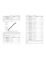
5.9 Group b8: AI/AO Correction
Code
Parameter Name
Setting Range
Default
b8-00
Ideal voltage of AI1
calibration 1
0.500~4.000 V
2.000V
b8-01
Sampling voltage of AI1
calibration 1
0.500~4.000 V
2.000V
b8-02
Ideal voltage of AI1
calibration 2
6.000~9.999 V
8.000V
b8-03
Sampling voltage of AI1
calibration 2
6.000~9.999 V
8.000V
b8-04
Ideal voltage of AI2
calibration 1
0.500~4.000 V
2.000V
b8-05
Sampling voltage of AI2
calibration 1
0.500~4.000 V
2.000V
b8-06
Ideal voltage of AI2
calibration 2
6.000~9.999 V
8.000V
b8-07
Sampling voltage of AI2
calibration 2
6.000~9.999 V
8.000V
b8-08
Ideal voltage of AI3
calibration 1
0.500~4.000 V
2.000V
b8-09
Sampling voltage of AI3
calibration 1
0.500~4.000 V
2.000V
b8-10
Ideal voltage of AI3
calibration 2
6.000~9.999 V
8.000V
b8-11
Sampling voltage of AI3
calibration 2
6.000~9.999 V
8.000V
These parameters are used to correct the AI to eliminate the impact of AI zero offset and gain.
They have been corrected of delivery. When you resume the factory values, these parameters will be
restored to the factory-corrected values. Generally, you need not perform correction in the applications.
Measured voltage indicates the actual output voltage value measured by instruments such as the multimeter.
Displayed voltage indicates the voltage display value sampled by the frequency inverter. For details, refer to
the voltage displayed before AI correction in group U0.
During correction, send two voltage values to each AI terminal, and save the measured values and displayed
values to the function codes b8-00 to b8-11. Then the frequency inverter will automatically perform AI zero
offset and gain correction.
If the input voltage and the actual voltage sampled by the HC drive are inconsistent, perform correction on
site. Take AI1 as an example. The on-site correction is as follows:
1.
Send a voltage signal (approximately 2 V) to AI1.
2.
Measure the AI1 voltage and save it to b8-00.
3.
View the displayed value of U0-21 and save the value to b8-01.
4.
Send a voltage signal (approximately 8 V) to AI1.
5.
Measure AI1 voltage and save it to b8-02.
6.
View the displayed value of U0-21 and save the value to b8-03.
At correction of AI2 and AI3, the actually sampled voltage is respectively queried in U0-22 and U0-23.
For AI1 and AI2, 2 V and 8 V are suggested as the correction voltages. For AI3, -8 V and 8V are suggested.
5. Description of Function Codes
EM11 User’s Manual
76
Code
Parameter Name
Setting Range
Default
b8-12
Ideal voltage of AO1
calibration 1
0.500~4.000 V
2.000V
b8-13
Measured voltage of AO1
calibration 1
0.500~4.000 V
2.000V
b8-14
Ideal voltage of AO1
calibration 2
6.000~9.999 V
8.000V
b8-15
Measured voltage of
AO1calibration 2
6.000~9.999 V
8.000V
b8-16
Ideal voltage of AO2
calibration 1
0.500~4.000 V
2.000V
b8-17
Measured voltage of AO2
calibration 1
0.500~4.000 V
2.000V
b8-18
Ideal voltage of AO2
calibration 2
6.000~9.999 V
8.000V
b8-19
Measured voltage of AO2
calibration 2
6.000~9.999 V
8.000V
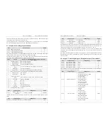
These parameters are used to correct the AO.
They have been corrected of delivery. When you store the factory default values, these parameters will be
restored to the factory-corrected values. Generally you needn’t perform correction in the applications.
Ideal target voltage indicates the theoretical output voltage of the frequency inverter. Measured voltage
indicates the actual output voltage value measured by instruments such as the multimeter.
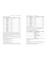
5.10 Group b9: Operation Panel and Display
Code
Parameter Name
Setting Range
Default
b9-00
STOP/RESET key function
0: STOP/RESET key enabled only in
operation panel control
1: STOP/RESET key enabled in any
operation mode
0
b9-01
MF.K Key function selection
0: MF.K key disabled
1: Switchover between operation panel
control and remote command control
(terminal or communication)
2: Switchover between forward rotation and
reverse rotation
3: Forward JOG
4: Reverse JOG
0
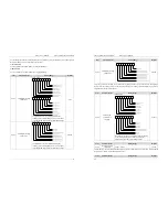
MF.K key refers to multifunctional key. You can set the function of the MF.K key by using this parameter.
You can perform switchover by using this key both in stop or running state.
0: MF.K key disabled
This key is disabled.
1: Switchover between operation panel control and remote command control
(terminal or
communication)
You can perform switchover from the present command source to the operation panel control (local
operation). If the present command source is operation panel control, this key is invalid.
2: Switchover between forward rotation and reverse rotation


