EM11 User’s Manual
5. Description of Function Codes
99
Code
Parameter Name
Setting Range
Default
C2-27
Acceleration/deceleration
time of simple PLC
Segment 12
0~3 0
C2-28
Running time of simple
PLC Segment 13
0.0s(h)~6553.5s(h) 0.0s
(h)
C2-29
Acceleration/deceleration
time of simple PLC
Segment 13
0~3 0
C2-30
Running time of simple
PLC Segment 14
0.0s(h)~6553.5s(h) 0.0s
(h)
C2-31
Acceleration/deceleration
time of simple PLC
Segment 14
0~3 0
C2-32
Running time of simple
PLC Segment 15
0.0s(h)~6553.5s(h) 0.0s
(h)
C2-33
Acceleration/deceleration
time of simple PLC
Segment 15
0~3 0
C2-34
Time unit of simple PLC
running
0: s (second)
1: h (hour)
0
5.17 Group C3: Swing Frequency, Fixed Length and Count
The swing frequency function is applied to the textile and chemical fiber fields and the applications where
traversing and winding functions are required.
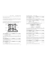
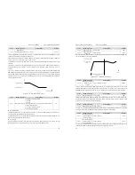
The swing frequency function indicates that the output frequency of the frequency inverter swings up and
down with the setting frequency as the center. The trace of running frequency at the time axis is shown in
the following figure.
The swing amplitude is set in C3-00 and C3-01. When C3-01 is set to 0, the swing amplitude is 0 and the
swing frequency does not take effect.
Diagram 5-29 Swing frequency control
Code
Parameter Name
Setting Range
Default
C3-00
Swing frequency
setting mode
0: Relative to the central frequency
1: Relative to the maximum frequency
0
This parameter is used to select the basic value of the swing amplitude.
0: Relative to the central frequency (b0-07 frequency source selection)
5. Description of Function Codes
EM11 User’s Manual
100
It is variable swing amplitude system. The swing amplitude varies with the central frequency (setting
frequency).
1: Relative to the maximum frequency (b0-13 maximum output frequency)
It is fixed swing amplitude system. The swing amplitude is fixed.
Code
Parameter Name
Setting Range
Default
C3-01
Swing frequency
amplitude
0.0%~100.0% 0.0%
C3-02
Textile jump
frequency amplitude
of Swing running
0.0%~50.0% 0.0%
This parameter is used to set the jump frequency amplitude of swing running. The swing frequency is
limited by the frequency upper limit and frequency lower limit.
If swing frequency is relative to the central frequency (C3-00 = 0), the actual swing amplitude
AW
=
b0-07 (Frequency source) ×C3-01(Swing frequency amplitude).
If swing frequency is relative to the maximum frequency (C3-00 = 1), the actual swing amplitude
AW
=
b0-13 (Maximum frequency) ×C3-01(Swing frequency amplitude).
The jump frequency is relative to the percentage of swing frequency amplitude. That is to say, jump
frequency = Swing frequency running amplitude
AW
×C3-02 (Jump frequency amplitude).
If Swing frequency amplitude is relative to the central frequency (C3-00 = 0), the jump frequency is a
variable value.
If Swing frequency amplitude is relative to the maximum frequency (C3-00 = 1), the jump frequency is
a fixed value.
Code
Parameter Name
Setting Range
Default
C3-03
Swing frequency
cycle
0.1s~3000.0s 10.0s
C3-04
Triangular wave
rising time coefficient
0.1%~100.0% 50.0%
C3-03 specifies the time of a complete swing frequency cycle.
C3-04 specifies the time percentage of triangular wave rising time to C3-03 (Swing frequency cycle).
Triangular wave rising time = C3-03 (Swing frequency cycle) × C3-04 (Triangular wave rising time
coefficient, unit: s)
Triangular wave falling time = C3-03 (Swing frequency cycle) × (1 – C3-04 Triangular wave rising time
coefficient ,unit: s)
Code
Parameter Name
Setting Range
Default
C3-05
Set length
0m~65535 m
1000 m
C3-06
Actual length
0m~65535 m
0 m
C3-07
Number of pulses per
meter
0.1~6553.5 100.0
The above parameters are used for fixed length control.
The length information is collected by DI terminals. C3-06 (Actual length) is calculated by dividing the
number of pulses collected by the DI terminal by C3-07 (Number of pulses each meter).
When the actual length C3-06 exceeds the set length in C3-05, the DO terminal set with function “Length
reached” becomes ON.

