


ENGLISH
4 Code 9828093379 ed 00 05/2020
2.0 INTENDED USE
The compressor has been built to supply compressed air for industrial use.
The machine cannot be used in premises where there is a risk of fire or explosion, or where the activity performed can
release into the environment dangerous substances (for example: solvents, inflammable vapours, alcohol, etc.).
In particular the appliance cannot be used to produce air to be breathed by humans or used on direct contact with foodstuffs.
These uses are allowed if the compressed air produced is filtered by means of a suitable filtering system (Consult the
manufacturer for these special uses.)
This appliance must be used only for the purpose for which it was specifically designed.
All other uses are to be considered incorrect and therefore unreasonable.
The Manufacturer cannot be held responsible for any damage resulting from improper, incorrect or unreasonable use.
3.0 OPERATION
3.1 OPERATION FOR COMPRESSOR
The electric motor and the compressor unit are coupled by means of a belt transmission.
The compressor unit takes in the outside air through the suction valve. The intake air is filtered by the filter cartridge fitted
upstream from the intake valve.
Inside the compressor unit, the air and the lubricating oil are compressed and sent to the oil
separating tank where the oil is separated from the compressed air; the air is then filtered again by the oil separating
cartridge to reduce the amount of suspended oil particles to a minimum. The machine is fitted with a suitable air-cooling
system.
The machine is protected by a special safety thermostat: if the oil temperature reaches 120°C the machine cuts out
automatically.
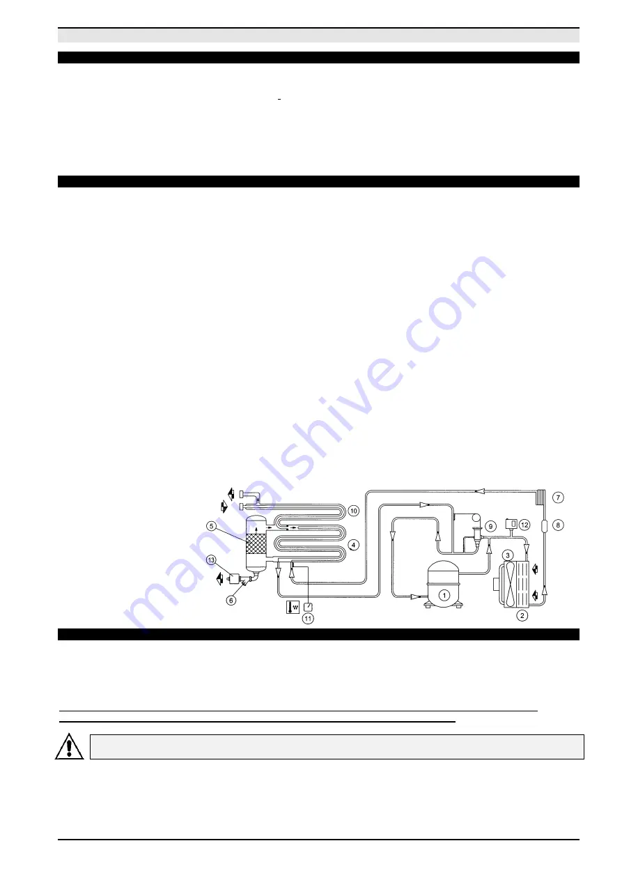
3.2 OPERATION FOR DRYER
At the moment of use the air flows from the tank to the drier and is then dried and sent to the distribution network. Dryer
operation is described below. The gaseous refrigerant coming from the evaporator (4) is sucked by the refrigeration
compressor (1) and it is pumped into the condenser (2). This one allows its condensation, eventually with the help of the fan
(3); the condensed refrigerant passes through the dewatering filter (8) and it expands through the capillary tube (7) and goes
back to the evaporator where it produces the refrigerating effect.
Due to the heat exchange with the compressed air which passes through the evaporator against the stream, the refrigerant
evaporates and goes back to the compressor for a new cycle.
The circuit is equipped with a bypass system for the refrigerant; this intervenes to adjust the available refrigerating capacity
to the actual cooling load.
This is achieved by injecting hot gas under the control of the valve (9): this valve keeps constant the pressure of the
refrigerant in the evaporator and therefore also the dew point never decreases below 0 °C in order to prevent the
condensate from freezing inside the evaporator.
The drier runs completely automatically; it is calibrated in the factory for a dew point of ~ 3 °C and therefore no further
calibrations are required.
DRYER FLOW DIAGRAM
4.0 GENERAL SAFETY STANDARDS
The appliance may be used only by specially trained and authorized personnel.
Any tampering with the machine or alterations not approved beforehand by the Manufacturer relieve the latter of
responsibility for any damage resulting from the above actions.
The removal of or tampering with the safety devices constitutes a violation of the European Standards on safety.
ATTENTION: UPSTREAM OF THE MACHINE INSTALL AN ISOLATOR KNIFE-SWITCH WITH AN AUTOMATIC
CUTOUT AGAINST CURRENT SURGES AND EQUIPPED WITH A DIFFERENTIAL DEVICE.
ALL WORK ON THE ELECTRIC PLANT, HOWEVER SLIGHT, MUST BE CARRIED OUT BY
PROFESSIONALLY SKILLED PERSONEL.
AIR INLET
AIR OUTLET
CONDENSATE
DRAIN


