Chandler Engineering AMETEK 7200 Скачать руководство пользователя страница 9

PREFACE     P

-


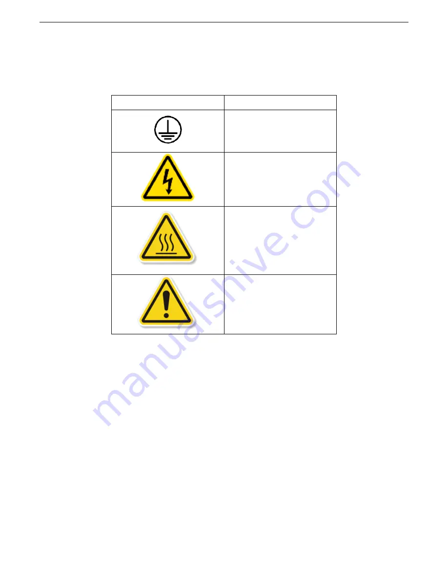
Symbols Used on Equipment 


Symbol 

Meaning 


Protective Conductor 
Terminal 


Hazardous Voltage Inside 
 
Disconnect power before 
opening 


Hot Surface 
Do Not Touch 
 
Allow to cool before 
servicing 


Documentation must be 

consulted in all cases 
where this caution symbol 
is marked. 


Where to Find Help 

 
Training classes are available in your laboratory and at Chandler Engineering. For more 
information, contact our sales department at Chandler Engineering. In the event of problems, 
your local sales representative will be able to help, or you can contact the personnel at 
Chandler Engineering using the following: 


Telephone: 

1-918-250-7200 


FAX:    


1-918-459-0165 


E-mail:    

[email protected] 


Website:   

www.chandlereng.com 


Содержание AMETEK 7200

Страница 1: ...MENT HYDRATION ANALYZER Part Number 7200 1050 Revision M Apr 2021 2001 North Indianwood Avenue Broken Arrow OK 74012 U S A Telephone 1 918 250 7200 Fax 1 918 459 0165 E mail chandler sales ametek com...

Страница 2: ...publisher assumes no responsibility for errors or omissions Neither is any liability assumed for damages resulting from the use of the information contained herein This publication contains the follo...

Страница 3: ...rol System 1 3 Installing the CHA Vessel and Stand 1 3 Installing the Pressure Transducers 1 4 Connecting Utilities 1 4 Section 2 Operating Instructions 2 1 Front Panel Valves Indicators and Controls...

Страница 4: ...ell No Gas Injection 2 15 Cell Open Constant H2O Confining Pressure Until Gas Injection 2 16 Interpretation of Results 2 16 Pre start up Checks 2 17 Powering On 2 18 Filling the System with Test Fluid...

Страница 5: ...decreases due to cement shrinkage and loss of fluid communication through the sample during hydration Gas mass flow meters are used to measure the flow rate of the gas entering the cement slurry and t...

Страница 6: ...10 89 atm Min 20 psig 0 138 MPa 138 kPa 1 38 bar 1 36 atm Air Supply Inlet Max 160 psig 1 103 MPa 11 03 bar 10 89 atm Min 20 psig 0 138 MPa 138 kPa 1 38 bar 1 36 atm Measurement Accuracy 0 2 of Full...

Страница 7: ...ate Measurement Accuracy 1 2 of Full Scale 0 06 sccm at manufacturer calibrated inlet conditions of Inlet Pressure 1000 psig 6 895 MPa 68 95 bar 68 05 atm Temperature 70o F 21o C Flow Rate Measurement...

Страница 8: ...the power cord Post signs where the instrument is being operated to warn non operating personnel Read and understand instructions before attempting operation Observe warning and caution notes through...

Страница 9: ...ution symbol is marked Where to Find Help Training classes are available in your laboratory and at Chandler Engineering For more information contact our sales department at Chandler Engineering In the...

Страница 10: ......

Страница 11: ...t to back Elevate the forks in such a manner as to be able to safely slide the CHA onto the forks Lift the instrument in such a manner as to keep it level Do not attempt to manually lift or carry the...

Страница 12: ...wrench on flats of Diaphragm Stem of CHA vessel Wrench 1 2 open end as backup wrench on body of fittings for 1 4 OD tubing Wrench 9 16 open end for nut of fittings for 1 4 OD tubing Wrench 7 16 open...

Страница 13: ...and is necessary to contain the pressure in the vessel If the vessel is pressurized without being tightly clamped in the Stand the end caps will be blown off the ends of the vessel s body possibly cau...

Страница 14: ...the GAS VENT connection on the back of the CHA instrumentation cabinet and run this tube to a vent hood or outside the building if desired See the Utilities and Environmental Requirements earlier in...

Страница 15: ...Supply Pressure gauge This 0 3000 psig 0 20700 kPa dial pressure gauge indicates the N2 GAS SUPPLY PRESSURE downstream of the GAS SUPPLY valve H2O Confining Pressure regulator This hand adjusted sprin...

Страница 16: ...2 2 SECTION 2 OPERATING INSTRUCTIONS Figure 1 Front Panel...

Страница 17: ...air from that portion of the instrument It is then closed vertical position and must remain closed during any CHA test Air Supply Pressure Gauge This 0 160 psig 0 1103 kPa dial pressure gauge indicate...

Страница 18: ...ir from that portion of the instrument During the test and during any assembly disassembly or removal of the CHA Vessel and Stand this valve must be manually CLOSED to prevent continued pressurization...

Страница 19: ...ice the Main and Plot tabs near the upper left corner of the screen Figure 2 Main Display Menu Bar File menu Log Data There are two modes for logging data to a file When Log Data is selected the Manua...

Страница 20: ...on is clicked This window allows the user to add comments about the test to the data file The User Comment is saved to the log file along with the corresponding data points Figure 3 Main Screen while...

Страница 21: ...Maximum Temperature Oven Temperature and Cement Temperature When a limit is changed the OK button must be pressed for the software to accept the new value These limits are the triggers for the pop up...

Страница 22: ...A uses very low flow rate flow meters to measure gas injected N2 Flow Rate and to indicate the relative expansion contraction of the cement H2O Flow Rate room temperature changes could affect the meas...

Страница 23: ...sel This can be used as an approximate indication of the volume of gas which migrates into the cement after opening the Gas Injection Valve H2O Confining Valve The H2O Confining Valve control is used...

Страница 24: ...re Pressure value This mode is for use when conducting a test according to the Procedure 2 of Type 3 experiment see the discussion of Basic Tests Performed with the model 7200 CHA later in this sectio...

Страница 25: ...psig and the Pressure Hysteresis to set to 15 psig and the valves switch automatically upon the Pore Pressure reaching 400 psig the Pore Pressure must increase back up to 415 psig for the valves to s...

Страница 26: ...ner of the screen Figure 7 Plot Screen Up to 8 different parameters can be shown on this real time plot To choose which parameters are plotted right click on the plot and choose the parameter desired...

Страница 27: ...d rescale the plot manually turn x axis tracking on and off print and save the plot and hide or show various details The Manual Axis Scaling pop up screen is shown below in Figure 8 Figure 8 Manual Ax...

Страница 28: ...nfigure I O Connections dialog a new entry will appear You can name this connection anything but the remainder of this discussion assumes it is named CHA DAQ If the Oven Temperature Controller uses et...

Страница 29: ...e shear stress on the inside of the test section The shear area within the well is determined as follows The dimensions and shear area of the CHA test section are listed as follows Internal diameter 1...

Страница 30: ...above the sample reaches the preset Gas Injection Pressure 250 psi close the H2O Confining valve and open the Gas Injection valve to allow the gas to enter the cell throughout the remainder of the te...

Страница 31: ...s Prior to start up the following checks should be made to ensure that 1 Lines pressure tubing are in place and secure 2 Pressurized fluid sources are connected to the CHA 3 Vent lines are connected t...

Страница 32: ...face of the washer against the rubber diaphragm by tightening the threaded nut Item 9 This is more easily done by first folding the diaphragm upward and out of the way and using the 7 8 flat wrench in...

Страница 33: ...remove the plug from the GAS INJECTION fitting on the bottom of the vessel s stem inside the oven and quickly connect the Gas Injection tubing coming out of the oven wall to this GAS INJECTION fitting...

Страница 34: ...ould fall into place in the slot of the vertical bar of Item 17 d Rotate the hand knob Item 24 CW clockwise and tighten until it is tight by hand only tightly clamping the CHA Vessel in place in the s...

Страница 35: ...d the Cement Temperature inside are allowed to heat and reach the desired test temperature Oven Temperature during the test 30 The test should be run long enough for it to be obvious based upon the Po...

Страница 36: ...ing f Raise vessel slightly from lower arm Item 17 and tilt it and lift it to remove it from stand 6 Disassemble the CHA vessel as necessary Pull the upper end plug with RTD if still connected and met...

Страница 37: ...SECTION 2 OPERATING INSTRUCTIONS 2 23 12 Turn off the software using the File Exit command 13 Turn off power to the instrument...

Страница 38: ......

Страница 39: ...rrosion Prevent the unused CHA Vessel sample tubes from corroding that may prevent sealing on the ends These are made of carbon steel and will rust easily if not protected Cleaning The CHA was designe...

Страница 40: ...which the instrument is operated 2 As previously mentioned use a new diaphragm Item 6 on the 7200 1010 CHA Vessel assembly drawing for each test 3 As mentioned in the System Shut down and Post test Cl...

Страница 41: ...near 0 5VDC signal corresponding to 0 1000 psig This signal is read by the data acquisition module and the CHA Control software converts this voltage to a pressure value according to the calibration s...

Страница 42: ...ure is close to the limit Enter the known pressure in the Span control and click the Sample button below the control The software will calculate Slope and Intercept The pressure can be removed and the...

Страница 43: ...rate units of sccm by this full scale output voltage and enter that scaling factor sccm Volt in the Slope control For example if the full scale output voltage for the transducer is 5 0 Volts DC then S...

Страница 44: ...at the maximum deviation in resistance output is 0 06 ohms 0 15 C at 0 C 0 13 ohms 0 35 C at 100 C and 0 20 ohms 0 55 C at 200 C Each RTD is provided with a factory calibration at 0 C 100 C and 200 C...

Страница 45: ...perature use Step 5 of the procedure 7200 1060 to calibrate it to match the Cement Temperature sensor RTD after first calibrating the Cement Temperature according to the previous section If you wish t...

Страница 46: ...tion screen as mentioned above Pore Pressure H2O Confining Pressure Pore Pressure H2O Confining Flow Rate and Gas Injection Flow Rate 2 All the pressure temperature and flow rate measurements should b...

Страница 47: ...en the H2O Confining Pressure and the Pore Pressure Pore Pressure is not affected by H2O Confining Pressure Check to see that the appropriate valves are opened Check for plugged tubing in the lines be...

Страница 48: ...5 2 SECTION 5 TROUBLESHOOTING GUIDE This page is intentionally left blank...

Страница 49: ...00 ACCESS Accessory Kit 7200 CHA 7200 SP Spares Kit CHA 1 yr 7200 1010 SK Seals Kit CHA Vessel 7200 TOOLS Tool Kit CHA For parts not included in the above Spare Parts Kits see the assembly drawings an...

Страница 50: ...6 2 SECTION 6 REPLACEMENT PARTS This page is intentionally left blank...

Страница 51: ...ydration Analyzer 7200 1010 Vessel w Stand CHA 7200 1010 1061 Proc Pressure Test CHA 7200 1020 Diagram Plumbing CHA 7200 1030 Diagram Wiring CHA 7200 1042 Proc CHA Control Software Installation 7200 1...

Страница 52: ...6 2 SECTION 6 REPLACEMENT PARTS This page is intentionally left blank...

Страница 53: ...1 JS A 1 A BREAK EDGES DEBURR UON DIMS ARE IN INCHES 1 PLC 0 030 2 PLC 0 010 3 PLC 0 005 ANGL 1 2 SURFACE FINISH 63 RMS THIRD ANGLE PROJECTION 2 1 2000 2 1 2007 2 2 2007 SHEET 1 OF 6 TITLE BLOCK REV 3...

Страница 54: ...ING SIZE D REV Y CEMENT HYDRATION ANALYZER PN 7200A PROJ DRAWN DAH MFG JJM ENGR JJM TYPE STRUCT THIS DOCUMENT AND THE DRAWINGS AND TECHNICAL DATA CONTAINED HEREON ARE THE PROPERTY OF CHANDLER ENGINEER...

Страница 55: ...F 6 TITLE BLOCK REV 3 CHANDLER ENGINEERING SIZE D REV Y CEMENT HYDRATION ANALYZER PN 7200A PROJ DRAWN DAH MFG JJM ENGR JJM TYPE STRUCT THIS DOCUMENT AND THE DRAWINGS AND TECHNICAL DATA CONTAINED HEREO...

Страница 56: ...REV 3 CHANDLER ENGINEERING SIZE D REV Y CEMENT HYDRATION ANALYZER PN 7200A PROJ DRAWN DAH MFG JJM ENGR JJM TYPE STRUCT THIS DOCUMENT AND THE DRAWINGS AND TECHNICAL DATA CONTAINED HEREON ARE THE PROPER...

Страница 57: ...CHANDLER ENGINEERING SIZE D REV Y CEMENT HYDRATION ANALYZER PN 7200A PROJ DRAWN DAH MFG JJM ENGR JJM TYPE STRUCT THIS DOCUMENT AND THE DRAWINGS AND TECHNICAL DATA CONTAINED HEREON ARE THE PROPERTY OF...

Страница 58: ...8 2 80 H 6002 WSHR FLAT SS 6 10 81 H 6001 WSHR LOCK SS 6 12 82 H 6009 SCREW BHMS SS 6 32X0 250 PHIL 12 83 H 8001 WSHR LOCK SS 8 4 84 H 8014 SCREW BHMS SS 8 32X0 500 PHIL 4 85 H 25 003 NUT HEX SS 1 4...

Страница 59: ...RAWINGS AND TECHNICAL DATA CONTAINED HEREON ARE THE PROPERTY OF CHANDLER ENGINEERING COMPANY L L C REPRODUCTION OR DISSEMINATION IN ANY FORM EXCEPT AS EXPRESSLY AUTHORIZED BY THE OWNER IS FORBIDDEN TH...

Страница 60: ...Item no Part no Description Qty Units Material 1 6990 0034 TUBE SAMPLE CHA 1 ea carbon steel 2 7200 1010 02 CAP CHA UPPER 1 ea 316 SS 3 7200 1010 03 CAP CHA LOWER 1 ea 316 SS 4 7200 1010 04 RETAINER D...

Страница 61: ...______ liquid and N2 nitrogen gas See procedures Step Pressure Fluid Time Press Drop Temp Pass Fail no psig mins psi F 5 500 liquid 6 1000 liquid 7 1500 liquid 8 Release pressure liquid 9 500 liquid 1...

Страница 62: ...URE and GAS INJECTION ports Plug the top ports with Swagelok plugs or plumb valves to these ports 3 Open the H2O FILL PURGE port on the side of the upper cap by opening the valve plumbed to it or by l...

Страница 63: ...to pressurize it to 1000 psig With the valve open between the N2 source and the cell maintain this pressure for 5 minutes then close this valve between cell and gas booster and hold pressure for a mi...

Страница 64: ...PANEL ADJUST OUTLET MODIFY VALVE HANDLE SO THAT 300 302 SET TO 1200 psig AND SAFETY WIRE INSTALLED SET TO 1200 psig MINIMUM LENGTH 300 302 THESE SECTIONS OF TUBING SHOULD BE NOTE 1050 PSI SET TO AND S...

Страница 65: ...CHANDLER ENGINEERING...

Страница 66: ......

Страница 67: ...file to another folder in Step 1 above now copy this file back to the folder C Program Files Chandler Engineering CHA 5 Set up the network interface Ethernet LAN card of the computer to communicate wi...

Страница 68: ...with tubing connected and fill and purge with H2O as in preparation for the maximum pressure and temperature test with H2O c Set the Oven Temperature to a value slightly higher than room temperature...

Страница 69: ...RTD vs temperature block calibrator according to Step 5 a of Procedure 7200 1060 12 Calibrate Oven Temperature controller vs Cement Temperature RTD according to Steps 5 b 5 k of Procedure 7200 1060 1...

Страница 70: ...in manual 28 Record all software setup cal values file copies 29 Record TCP IP settings file in Serial No file and in manual 30 Check computer remove source code etc 31 Install external panels take p...

Страница 71: ...to the CHA 6 Turn on the power switch to the CHA turn on the computer and run the CHA Control software Use the software to check for proper remote control of valves temperature setpoint etc 7 Test all...

Страница 72: ...orking Temperature of 325 F 163 C 4 F 2 C using N2 gas and H2O Ensure that the system is leak free at these conditions See the Users Manual for instructions on Filling the System with Test Fluids and...

Страница 73: ...ped with the instrument with a note to designate that this is for the Cement Temperature 25 Record the Serial Number of the Cabinet Temperature RTD on the first page of this Procedure Report and file...

Страница 74: ...or other software not purchased by the customer 31 Install any external panels removed during testing and take pictures of the system including internal wiring and plumbing details File pictures in i...

Страница 75: ...ften are ________________________________________________ ______________________________________________________________________________ Other comments ________________________________________________...

Страница 76: ...cut out postcards on dotted lines...

Страница 77: ...bnormal usage faulty installation im proper maintenance or any repairs other than those provided by authorized Chandler Engineering personnel This warranty is in lieu of all other warranties expressed...

Отзывы: