background image

NOTICE TO CANADIAN USERS

NOTICE:

  The  Industry Canada  label  identifies certified equipment.    This  certification means that  the

equipment meets telecommunications network protective, operation and safety requirements as prescribed

in  the  appropriate  Terminal Equipment Technical Requirements document(s). The Department does  not

guarantee the equipment to the user’s satisfaction.
Before installing this equipment, users should ensure that it is permissible to be connected to the facilities of

the local telecommunications company.  The equipment must also be installed using an acceptable method of

connection. The customer should be aware that compliance with the above conditions may  not  prevent

degradation of service in some situations.
Repairs to certified equipment should be coordinated by  a representative designated by the supplier.  Any

repairs  or  alterations made  by  the user  to  this  equipment,  or  equipment  malfunctions, may give  the

telecommunications company cause to request the user to disconnect the equipment.
Users should ensure for their own protection that  the  electrical  ground  connections  of  the power utility,

telephone lines and internal metallic water pipe system, if present, are connected together. This precaution

may be particularly important in rural areas.

Caution:

  Users  should not attempt  to  make such  connections  themselves,  but  should  contact  the

appropriate electric inspection authority, or an electrician, as appropriate.

NOTICE:

 The 

Ringer Equivalence Number 

(REN) assigned to each terminal device provides an indication

of the maximum number of terminals allowed to be connected to a telephone interface.  The termination on

any interface may consist of any combination of devices subject only to the requirement that the sum of the

Ringer Equivalence Numbers of all the devices does not exceed 5.

COPYRIGHT

©

 2004

ALL RIGHTS RESERVED

This document is protected by copyright and may not be copied or adapted without the prior written consent

of LiftMaster.  This documentation contains information proprietary to LiftMaster and such information may

not be distributed without the prior written consent of LiftMaster.  The software and firmware included in

the LiftMaster product as they relate to this documentation are also protected by copyright and contain

information proprietary to LiftMaster.

FOR TECHNICAL SUPPORT OR TO ORDER REPLACEMENT PARTS, CALL OUR TOLL FREE NUMBER:

(800) 528

-2806

Monday thru Friday 5 AM – 6 PM, Saturday, 7 AM – 3:30 PM (PST)

Visit us at 

www.liftmaster.com

Содержание ESTATE SERIES SW 2000-X3

Страница 1: ...3 HEAVY DUTY HIGH CYCLE SWING GATE OPERATOR MODEL SW 2000 X3 IS FOR VEHICULAR PASSAGE GATES ONLY NOT INTENDED FOR PEDESTRIAN PASSAGE GATE USE 3 YEAR WARRANTY Serial _____________________ located on el...

Страница 2: ......

Страница 3: ...__________________________________ 9 G USING MANUAL CONTROLS _____________________________________________________________ 9 H GATE ARM INSTALLATION ___________________________________________________...

Страница 4: ...eft Gate Limit Cam_____________________________________________________12 Figure 10 Gate Sensitivity Adjustments Location ___________________________________________13 Figure 11 Control Board Wiring _...

Страница 5: ...the gate is obstructed Interrupt Bar input is included for use with edge sensors Cycle counter is able to initiate a service request call at a predetermined number Event recording memory keeps track o...

Страница 6: ......

Страница 7: ...operator safety features monthly The gate MUST reverse on contact with a rigid object or stop when an object activates the non contact sensors After adjusting the force or the limit of travel retest...

Страница 8: ...et of the system Even if you have a good earth ground you should try to discharge any static before handling the circuit boards WARNING Damage caused by static discharge and lightning is not covered b...

Страница 9: ...Rev F Doc 01 20099 3 of 42 PART 1 SITE PREPARATION A LOCATION AND LAYOUT Figure 1 Gate Operator Layout Options...

Страница 10: ...the gate operator and the dynamic forces created by the moving gate LiftMaster recommends a pad 24 wide by 27 long by 30 deep 2 The operator must be level and parallel to the gate so the pad should b...

Страница 11: ...om the telephone company termination block through the conduit to J9 on the control board Polarity is not important NOTE Do not run telephone and AC power wires in the same conduit G OTHER CONNECTIONS...

Страница 12: ...6 of 42 Doc 01 20099 Rev F PART 2 SYSTEM INSTALLATION A GATE AND PHOTO SENSOR LAYOUT Figure 3 Photo Sensor Layout...

Страница 13: ...sengage and remove quick disconnect arm cap from the output shaft see Figure 7 2 Remove 4 protective bolts holding the cover on lift off the cover and set aside 3 Remove the assembly kit and parts 4 R...

Страница 14: ...ING GATE OPEN DIRECTION SWITCHES S2 AND S3 Figure 5 Gate Direction and UPS Low Battery Switch Locations NOTE For swing gate operation controls are Left Clockwise and Right Counterclockwise Switch S2 s...

Страница 15: ...N LIMIT if one of the limit switches is engaged NOTE If the LEDs do not follow this pattern the controller board may not be working correctly Stop installation and call LiftMaster Technical Support fo...

Страница 16: ...ust 1 Attach gate anchor to gate by welding or using hardware not supplied 2 Using manual controls move the swing arm cap assembly until it points roughly to the anchor See Figure 7 3 Measure and cut...

Страница 17: ...0099F1 Figure 8 Setting Right Gate Limit Cam 1 Make sure that switch S2 is set to the Right position 2 Turn on gate operator power switch 3 Using manual CLOSE and STOP move the gate to its proper clos...

Страница 18: ...per open limit position 4 Loosen the clamp on the bottom limit cam and turn the cam clockwise until it just barely closes the limit switch 5 Retighten the clamp Do not overtighten 6 Using manual CLOSE...

Страница 19: ...mum sensitivity is full clockwise and maximum sensitivity is full counter clockwise These adjustments must be made while the gate is in motion Before starting the adjustments verify that the Left and...

Страница 20: ...until the gate stops or backs up when tugged and has the desired sensitivity Right Gate Motion Adjustment R69 1 Open the gate fully then initiate closing the gate 2 Wait 4 to 5 seconds then lightly b...

Страница 21: ...Figure 11 Control Board Wiring GROUND LUG EXTERNAL GROUND SEE SITE PREPERATION O P T I O N O P T I O N O P T I O N O P T I O N LOOP SENSOR LOOP SENSOR LOOP SENSOR LOOP SENSOR OUTSIDE INTERRUPT SENSE...

Страница 22: ...erminal stops the gate and prevents all commands from having any effect Manual Open does not activate the Reclose Timer IMPORTANT As per UL325 standards install the Manual Input and Fire switches in t...

Страница 23: ...RT Up to 3 30 0 250 Seconds 0 Disabled 09 Not Used 10 Not Used 11 Obstruction Sense Backup Closing Up to 3 12 12 499 Inches See note below 12 Obstruction Sense Backup Opening Up to 3 12 12 499 Inches...

Страница 24: ...is no slack in the closed gate due to loose chain or parts 5 Both gates open and close at the same time Bi Parting gates only 4 Gate Sensitivity and Obstruction Alarm Primary Obstruction Sensing per...

Страница 25: ...e Timer is not functional when the Manual OPEN command is used 8 Interrupt Loop and Anti Tailgating ATG When Exiting Gate Type is SWING Enter 1 in Programming Step 01 Inside Interrupt Loop When a vehi...

Страница 26: ...te should restart when the obstruction your hand is removed Coverage Area B Inside Closed Coverage Stand inside the fence line While the gate is moving put your hand or arm through the Outside Photo S...

Страница 27: ...of 42 11 Interrupt Bar Edge Sensor While the gate is opening push on the Interrupt Bar Edge Sensor The gate should stop and reverse a few inches 12 Maglock Verify that the Maglock activates when the...

Страница 28: ...this assembly aside 3 Install clear cover on gate operator control box 4 Make sure that gate operator unit power switch is turned on 5 Install gate operator cover and secure with four bolts 6 Replace...

Страница 29: ......

Страница 30: ...boards These boards simply plug into the control board and interface with Interrupt Shadow and Exit loop sensors The add on boards can be ordered pre installed or can be installed in existing model SW...

Страница 31: ...t measure 100VAC to 130VAC CAUTION HIGH VOLTAGE Measure with care Fault Causes Refer to the end of trouble shooting section 1 OPERATOR IS DEAD When the unit power switch is cycled the 7 segment displa...

Страница 32: ...Setting the Gate Type to SWING or LINEAR causes Interrupt loops or photo sensors to stop the gate when a vehicle approaches from the inside For safety reasons the gate normally operates this way 9 GAT...

Страница 33: ...ILGATE DOES NOT WORK For safety reasons ATG is not functional with Gate Types SWING and LINEAR 18 INTERRUPT LOOP DOES NOT ACT PROPERLY 1 Improper Gate Type setting programming step 1 2 Bad loop sensor...

Страница 34: ...d or unsupervised motor UL325 requirement 5 Limit switch staying closed when gate is supposed to move caused by a broken V belt defective limit switch or defective limit cams 6 Maximum motor run time...

Страница 35: ...Clear obstruction and cycle the gate 3 IF OPEN MTR LED IS TURNED ON 1 The motor thermal overload switch is popped 2 The wires connecting the motor to the Control Board are disconnected 3 Bad motor 4 B...

Страница 36: ...shaft Tighten set screws if loose 5 Limit switches contacts must bounce back rapidly when they are pressed and released 6 Belt Check for wear and tension 25 to 30 lb Adjust the AC motor up or down to...

Страница 37: ...ce Schedule 3 Disconnect Drag Link from Anchor then loosen mounting bolt and remove Swing Arm Cap Assembly and Drag Link Assembly from drive shaft Set this assembly aside 4 Push and pull the Gate to e...

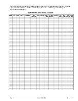
Страница 38: ...e maintenance schedule Write the inspection date in the left hand box and check the boxes across as you perform your maintenance procedures MAINTENANCE SCHEDULE TABLE Date Arm Gate Chain Sprocket Limi...

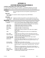
Страница 39: ...ndicates the gate is moving to the left MTR RIGHT Indicates the gate is moving to the right RECV Indicates data is being received from the other unit in a Master Slave system XMIT Indicates data is be...

Страница 40: ...ate Action allows a single command to both open and close the gate Activation opens the gate which remains open until another command is received A CYCLE command when the gate is fully open closes the...

Страница 41: ...and deactivation restarts the gate Outside Photo Sensor Activation stops a closing gate and deactivation restarts the gate IF GATE TYPE IS SLIDE OR BARRIER Inside Photo Sensor Activation stops an open...

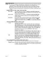
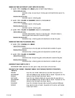
Страница 42: ...utive obstruction faults LOW BATTERY NO AC POWER TB18 LOW BATTERY Activation fully opens or closes the gate depending the setting of Switch S3 NO AC POWER Activation registers the date and time of pow...

Страница 43: ...an incline and not worry about sacrificing downhill gate sensitivity INRUSH Adjustable pot controls the delay in sensitivity to gate R203 obstructions This delay in sensitivity prevents the initial m...

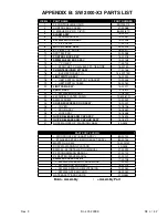
Страница 44: ...CABLE 94 20160 20 LIMIT CAM ASSY 75 20011 21 SHAFT ASSY 72 18512 22 SW2000 MAIN SHAFT 11 18140 23 40 NICKEL PLATED CHAIN 19 40081 N 24 SW2000 SHELF 10 20049 25 COVER W ACCESS DOOR ASSY 75 20029 26 CO...

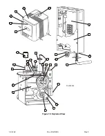
Страница 45: ...39 of 42 Doc 01 20099 Rev F 1 2 3 8 4 5 7 6 9 10 11 12 13 14 15 16 18 17 20 21 22 23 24 19 30 01 20099F4 29 25 26 31 27 28 Figure 19 Exploded View...

Страница 46: ...ystem when lit Limit switch A switch which its closure indicates the gate has reached its open or close limit causing the gate to stop There are two limit switches open and close Limit cam An object w...

Страница 47: ...s soon as possible When you are notified you will be given the opportunity to correct the problem and informed of your right to file a complaint with the FCC In the event that any repairs are ever nee...

Страница 48: ...ternal metallic water pipe system if present are connected together This precaution may be particularly important in rural areas Caution Users should not attempt to make such connections themselves bu...

Отзывы: