15
F.200/TITAN 200/MAR 97
15. Close the front guard and press CLEAR. This will
raise the knife and clamp to the up position.
16. Turn the power off and disconnect the machine
power cord.
17. Tighten all knife bolts securely.
18. Plug in the power cord and turn the power on.
Make a test cut through a full lift of paper and make
minor adjustments if necessary by repeating steps 9
through 17. NOTE: If the knife ends cut but the middle
doesn’t, you could have dips or uneven spots in the
knife and/or cutting stick. These can be eliminated by
placing 1/2” strips of paper in the table slot beneath
the cutting stick to shim it.
19. Send the dull knife to a knife grinder. Do not attempt
to sharpen your own knives! See the Knife Tips section
(pg. 23) to determine the knife bevel angle.
False Clamp Plate (Optional)
To prevent marking on pressure sensitive jobs, a false
clamp plate is available as an optional item for your
machine. This plate attaches to the bottom of the
clamp. It is secured with wing nuts on studs that pass
through the top of the clamp.
To install:
1. Make sure the knife and clamp are in the up position.
If they are not, turn on the power using the red and
yellow main power switch, close the front guard, and
press the CLEAR button. This will preset the
backgauge and send the knife and clamp up.
2. Turn the power off and disconnect the power cord.
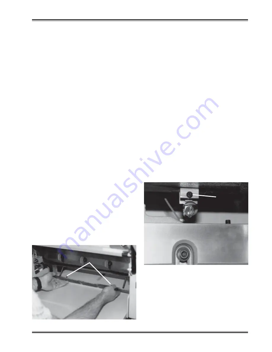
3. Open the front guard and slide the false clamp plate
under the knife and clamp (fig. 17), and slide the plate
up into position with the locator pins toward the front of
the machine. The locator pins insert into holes in the
bottom front of the clamp.
4. Hold the plate in position and secure with the wing
nuts provided.
5. Change the false clamp setting of the machine to
ON to prevent the backgauge from crashing into
the false clamp plate. This is done in the Maintenance
Mode/Parameters/False Clamp screen. For more
details on how to do this, see the Operating Controls/
Maintenance Mode/Parameters section (pg. 20).
NOTE: The minimum cut with the false clamp plate
attached is 1-3/4”
Line Light
The Titan 200 is equipped with two lights which provide
a line of light on the paper in the approximate location
of where the paper will be cut. The lights come on when
power to the machine is turned on. The light from each
bulb reaches the table after passing between the knife
and clamp. Each light is focused with a socket head
capscrew (fig. 18).
To Adjust:
1. Place a wide sheet of paper on the cut stick to view
the line light.
2. Using a 3/16” hex allen wrench, turn one of the cap
screws until you see a 1/16-1/8” beam. Note: it is best
to start by turning the screw clockwise. If the screw
turns all the way in before a line appears, begin turning
the screw counterclockwise.
3. Similarly, turn the adjustment screw of the other
(fig. 18)
Line Light
Adjustment
Screw
(fig. 17)
Locator Pins
NOTICE: UNSUPPORTED PRODUCT!
NO TECHNICAL SUPPORT AVAILABLE!
NO REPAIR PARTS AVAILABLE!


