SECTION 3
CESSNA
EMERGENCY PROCEDURES
MODEL 172S NAV III
ELECTRICAL POWER SUPPLY SYSTEM
MALFUNCTIONS
(Continued)
EXCESSIVE RATE-OF-CHARGE (Continued)
Electronic components in the electrical system can be adversely
affected by higher than normal voltage. The alternator control unit
includes an overvoltage sensor circuit which will automatically
disconnect the alternator if the charge voltage increases to more
than approximately 31.75 volts. If the overvoltage sensor circuit
does not operate correctly, as shown by voltage more than 31.75
volts on the main battery bus voltmeter, the MASTER switch ALT
section should be set to the OFF position. Unnecessary electrical
equipment should be de-energized and the flight terminated as soon
as practical.
INSUFFICIENT RATE-OF-CHARGE
When the over-voltage sensor circuit, or other fault, opens the
alternator (ALT FIELD) circuit breaker and de-energizes the
alternator, a discharge (-) current will be shown on the main battery
ammeter and the low voltage annunciator (LOW VOLTS) will come
on. The ACU can de-energize the alternator due to minor
disturbances in the electrical system, resulting in a "nuisance"
opening of the ALT FIELD circuit breaker. If this happens, an
attempt should be made to energize the alternator system.
To energize the alternator system
1. MASTER Switch (ALT Only) - OFF.
2. Alternator Circuit Breaker (ALT FIELD) - CHECK IN.
3. MASTER Switch (ALT Only) - ON.
If the problem was a minor ACU disturbance in the electrical
system, normal main battery charging will start. A charge (+)
current will be shown on the main battery ammeter and the LOW
VOLTS annunciator will go off.
If the LOW VOLTS annunciator comes on again, there is an
alternator system problem. Do not repeat steps to energize the
alternator system. The electrical load on the battery must be
minimized (by de-energizing nonessential electrical equipment and
avionics) because the battery can supply the electrical system for
only a short time. Reduce electrical load as soon as possible to
extend the life of the battery for landing. Land as soon as practical.
(Continued Next Page)
3-34 U.S.
172SPHAUS-03
Содержание 172S Skyhawk SP NAV III 2005
Страница 4: ......
Страница 6: ......
Страница 8: ......
Страница 10: ......
Страница 24: ...SECTION 1 CESSNA GENERAL MODEL 172S NAV III Figure 1 2 Weight Conversions Sheet 2 1 16 U S 172SPHAUS 00 ...
Страница 26: ...SECTION 1 CESSNA GENERAL MODEL 172S NAV III Figure 1 3 Length Conversions Sheet 2 1 18 U S 172SPHAUS 00 ...
Страница 28: ...SECTION 1 CESSNA GENERAL MODEL 172S NAV III Figure 1 4 Length Conversions Sheet 2 1 20 U S 172SPHAUS 00 ...
Страница 29: ...CESSNA SECTION 1 MODEL 172S NAV III GENERAL Figure 1 5 Distance Conversions 172SPHAUS 00 U S 1 21 ...
Страница 31: ...CESSNA SECTION 1 MODEL 172S NAV III GENERAL Figure 1 6 Volume Conversions Sheet 2 172SPHAUS 00 U S 1 23 ...
Страница 32: ...SECTION 1 CESSNA GENERAL MODEL 172S NAV III Figure 1 6 Volume Conversions Sheet 3 1 24 U S 172SPHAUS 00 ...
Страница 33: ...CESSNA SECTION 1 MODEL 172S NAV III GENERAL Figure 1 7 Temperature Conversions 172SPHAUS 00 U S 1 25 ...
Страница 35: ...CESSNA SECTION 1 MODEL 172S NAV III GENERAL Figure 1 9 Volume to Weight Conversion 172SPHAUS 00 U S 1 27 ...
Страница 36: ...SECTION 1 CESSNA GENERAL MODEL 172S NAV III Figure 1 10 Quick Conversions 1 28 U S 172SPHAUS 00 ...
Страница 38: ......
Страница 60: ......
Страница 64: ......
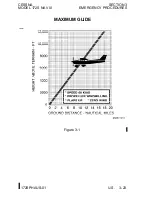
Страница 83: ...CESSNA SECTION 3 MODEL 172S NAV III EMERGENCY PROCEDURES MAXIMUM GLIDE Figure 3 1 I172SPHAUS 01 U S 3 23 ...
Страница 100: ......
Страница 148: ......
Страница 157: ...CESSNA SECTION 5 MODEL 172S NAV III PERFORMANCE Figure 5 2 Temperature Conversion Chart 172SPHAUS 00 U S 5 11 ...
Страница 170: ......
Страница 172: ......
Страница 194: ......
Страница 198: ......
Страница 294: ......
Страница 296: ......
Страница 320: ...SECTION 9 SUPPLEMENTS CESSNA SUPPLEMENT 3 MODEL 172S NAV III Figure S3 1 FAA APPROVED S3 8 U S 172SPHAUS S3 00 ...
Страница 366: ......
Страница 408: ......
Страница 422: ......

