


SECTION 7
CESSNA
AIRPLANE AND SYSTEMS DESCRIPTION
MODEL 172S NAV III
AIRFRAME
(Continued)
The empennage (tail assembly) consists of a conventional vertical
stabilizer, rudder, horizontal stabilizer, and elevator. The vertical
stabilizer consists of a spar, formed sheet metal ribs and reinforce-
ments, a wraparound skin panel, formed leading edge skin and a
dorsal. The rudder is constructed of a formed leading edge skin and
spar with attached hinge brackets and ribs, a center spar, a wrap
around skin, and a ground adjustable trim tab at the base of the
trailing edge. The top of the rudder incorporates a leading edge ex-
tension which contains a balance weight.
The horizontal stabilizer is constructed of a forward and aft spar,
ribs and stiffeners, center, left, and right wrap around skin panels,
and formed leading edge skins. The horizontal stabilizer also
contains the elevator trim tab actuator.
Construction of the elevator consists of formed leading edge skins,
a forward spar, aft channel, ribs, torque tube and bellcrank, left
upper and lower "V" type corrugated skins, and right upper and
lower "V" type corrugated skins incorporating a trailing edge cutout
for the trim tab. The elevator tip leading edge extensions
incorporate balance weights. The elevator trim tab consists of a
spar, rib, and upper and lower "V" type corrugated skins.
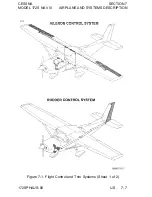
FLIGHT CONTROLS
The airplane's flight control system (Refer to Figure 7-1) consists of
conventional aileron, rudder, and elevator control surfaces. The
control surfaces are manually operated through cables and
mechanical linkage using a control wheel for the ailerons and
elevator, and rudder/brake pedals for the rudder.
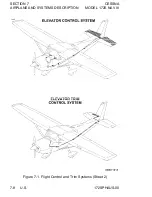
TRIM SYSTEM
A manually operated elevator trim system is provided (Refer to
Figure 7-1). Elevator trimming is accomplished through the elevator
trim tab by utilizing the vertically mounted trim control wheel in the
cockpit. Forward rotation of the trim wheel will trim nose down;
conversely, aft rotation will trim nose up.
7-6 U.S.
172SPHAUS-00
Содержание 172S Skyhawk SP NAV III 2005
Страница 4: ......
Страница 6: ......
Страница 8: ......
Страница 10: ......
Страница 24: ...SECTION 1 CESSNA GENERAL MODEL 172S NAV III Figure 1 2 Weight Conversions Sheet 2 1 16 U S 172SPHAUS 00 ...
Страница 26: ...SECTION 1 CESSNA GENERAL MODEL 172S NAV III Figure 1 3 Length Conversions Sheet 2 1 18 U S 172SPHAUS 00 ...
Страница 28: ...SECTION 1 CESSNA GENERAL MODEL 172S NAV III Figure 1 4 Length Conversions Sheet 2 1 20 U S 172SPHAUS 00 ...
Страница 29: ...CESSNA SECTION 1 MODEL 172S NAV III GENERAL Figure 1 5 Distance Conversions 172SPHAUS 00 U S 1 21 ...
Страница 31: ...CESSNA SECTION 1 MODEL 172S NAV III GENERAL Figure 1 6 Volume Conversions Sheet 2 172SPHAUS 00 U S 1 23 ...
Страница 32: ...SECTION 1 CESSNA GENERAL MODEL 172S NAV III Figure 1 6 Volume Conversions Sheet 3 1 24 U S 172SPHAUS 00 ...
Страница 33: ...CESSNA SECTION 1 MODEL 172S NAV III GENERAL Figure 1 7 Temperature Conversions 172SPHAUS 00 U S 1 25 ...
Страница 35: ...CESSNA SECTION 1 MODEL 172S NAV III GENERAL Figure 1 9 Volume to Weight Conversion 172SPHAUS 00 U S 1 27 ...
Страница 36: ...SECTION 1 CESSNA GENERAL MODEL 172S NAV III Figure 1 10 Quick Conversions 1 28 U S 172SPHAUS 00 ...
Страница 38: ......
Страница 60: ......
Страница 64: ......
Страница 83: ...CESSNA SECTION 3 MODEL 172S NAV III EMERGENCY PROCEDURES MAXIMUM GLIDE Figure 3 1 I172SPHAUS 01 U S 3 23 ...
Страница 100: ......
Страница 148: ......
Страница 157: ...CESSNA SECTION 5 MODEL 172S NAV III PERFORMANCE Figure 5 2 Temperature Conversion Chart 172SPHAUS 00 U S 5 11 ...
Страница 170: ......
Страница 172: ......
Страница 194: ......
Страница 198: ......
Страница 294: ......
Страница 296: ......
Страница 320: ...SECTION 9 SUPPLEMENTS CESSNA SUPPLEMENT 3 MODEL 172S NAV III Figure S3 1 FAA APPROVED S3 8 U S 172SPHAUS S3 00 ...
Страница 366: ......
Страница 408: ......
Страница 422: ......