


CESSNA
SECTION 7
MODEL 172S NAV III
AIRPLANE AND SYSTEMS DESCRIPTION
CABIN HEATING, VENTILATING AND DEFROSTING
SYSTEM
(Continued)
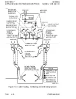
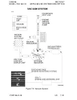
Separate adjustable ventilators supply additional air; one near each
upper corner of the windshield supplies air for the pilot and front
passenger, and two ventilators are available for the rear cabin area
to supply air to the rear seat passengers. There are additional
ventilators located in various positions in the cockpit.
PITOT-STATIC SYSTEM AND INSTRUMENTS
The pitot-static system uses a heated total pressure (pitot) head
mounted on the lower surface of the left wing, external static ports
mounted on the left side of the forward fuselage and associated
plumbing to connect the GDC 74A Air Data Computer and the
conventional pitot-static instruments to the sources.
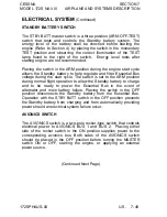
The heated pitot system uses an electrical heating element built in
the body of the pitot head. The PITOT HEAT control switch is found
on the switch panel below the lower LH corner of the PFD. The
PITOT HEAT circuit breaker (10 A) is found on the circuit breaker
panel at the lower LH side of the pilot panel.
A static pressure alternate source valve (ALT STATIC AIR) is
located next to the throttle control. The ALT STATIC AIR valve
provides static pressure from inside the cabin if the external static
pressure source becomes blocked.
If erroneous instrument readings are suspected due to water or ice
in the pressure line going to the standard external static pressure
source, the alternate static source valve should be pulled on.
Pressures within the cabin will vary with open heaters/vents and
windows. Refer to Section 5, Figure 5-1 (Sheet 2), for the Airspeed
Calibration, Alternate Static Source correction chart.
172SPHAUS-03
U.S. 7-59
Содержание 172S Skyhawk SP NAV III 2005
Страница 4: ......
Страница 6: ......
Страница 8: ......
Страница 10: ......
Страница 24: ...SECTION 1 CESSNA GENERAL MODEL 172S NAV III Figure 1 2 Weight Conversions Sheet 2 1 16 U S 172SPHAUS 00 ...
Страница 26: ...SECTION 1 CESSNA GENERAL MODEL 172S NAV III Figure 1 3 Length Conversions Sheet 2 1 18 U S 172SPHAUS 00 ...
Страница 28: ...SECTION 1 CESSNA GENERAL MODEL 172S NAV III Figure 1 4 Length Conversions Sheet 2 1 20 U S 172SPHAUS 00 ...
Страница 29: ...CESSNA SECTION 1 MODEL 172S NAV III GENERAL Figure 1 5 Distance Conversions 172SPHAUS 00 U S 1 21 ...
Страница 31: ...CESSNA SECTION 1 MODEL 172S NAV III GENERAL Figure 1 6 Volume Conversions Sheet 2 172SPHAUS 00 U S 1 23 ...
Страница 32: ...SECTION 1 CESSNA GENERAL MODEL 172S NAV III Figure 1 6 Volume Conversions Sheet 3 1 24 U S 172SPHAUS 00 ...
Страница 33: ...CESSNA SECTION 1 MODEL 172S NAV III GENERAL Figure 1 7 Temperature Conversions 172SPHAUS 00 U S 1 25 ...
Страница 35: ...CESSNA SECTION 1 MODEL 172S NAV III GENERAL Figure 1 9 Volume to Weight Conversion 172SPHAUS 00 U S 1 27 ...
Страница 36: ...SECTION 1 CESSNA GENERAL MODEL 172S NAV III Figure 1 10 Quick Conversions 1 28 U S 172SPHAUS 00 ...
Страница 38: ......
Страница 60: ......
Страница 64: ......
Страница 83: ...CESSNA SECTION 3 MODEL 172S NAV III EMERGENCY PROCEDURES MAXIMUM GLIDE Figure 3 1 I172SPHAUS 01 U S 3 23 ...
Страница 100: ......
Страница 148: ......
Страница 157: ...CESSNA SECTION 5 MODEL 172S NAV III PERFORMANCE Figure 5 2 Temperature Conversion Chart 172SPHAUS 00 U S 5 11 ...
Страница 170: ......
Страница 172: ......
Страница 194: ......
Страница 198: ......
Страница 294: ......
Страница 296: ......
Страница 320: ...SECTION 9 SUPPLEMENTS CESSNA SUPPLEMENT 3 MODEL 172S NAV III Figure S3 1 FAA APPROVED S3 8 U S 172SPHAUS S3 00 ...
Страница 366: ......
Страница 408: ......
Страница 422: ......


