


SECTION 7
CESSNA
AIRPLANE AND SYSTEMS DESCRIPTION
MODEL 172S NAV III
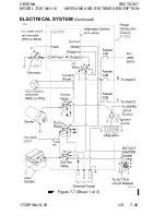
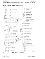
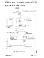
ELECTRICAL SYSTEM
(Continued)
ELECTRICAL SYSTEM MONITORING AND ANNUNCIATIONS
VOLTMETER
Voltage (VOLTS) indication for the Main and Essential buses is
provided at the bottom of the EIS ENGINE or SYSTEM pages,
labeled "M BUS E". Main bus voltage is shown numerically below
the "M". Essential bus voltage is displayed numerically below the
"E". The Main bus voltage is measured at the WARN circuit breaker
on the Crossfeed (X-FEED) bus. The Essential bus voltage is
measured at the NAV1 ENG circuit breaker on the Essential bus.
Normal bus voltages with the alternator operating shall be about 28
volts. When the voltage for either Main or Essential is at or below
24.5 volts, the numeric value and VOLTS text turns red. This
warning indication, along with the "LOW VOLTS" annunciation, is
an indication that the alternator is not supplying all the power that is
required by the aircraft. Indicated voltages between 24.5 and 28
volts may occur during low engine RPM conditions (Refer to note
under LOW VOLTAGE ANNUNCIATION).
AMMETER
Electric current (AMPS) indication for both the main and Standby
batteries is provided at the bottom of the EIS ENGINE or SYSTEM
pages, labeled "M BATT S". Main battery current is numerically
displayed below the "M". Standby battery current is displayed
numerically below the "S". A positive current value (shown in
white) indicates that the battery is charging. A negative current
value (shown in amber) indicates that the battery is discharging. In
the event the alternator is not functioning or the electrical load
exceeds the output of the alternator, the main battery ammeter
indicates the main battery discharge rate.
In the event that Standby battery discharge is required, normal
discharge should be less than 4 Amps. After engine start, with the
STBY BATT switch in the ARM position, the Standby Battery
ammeter should indicate a charge showing correct charging of
Standby Battery System.
(Continued Next Page)
7-50 U.S.
172SPHAUS-00
Содержание 172S Skyhawk SP NAV III 2005
Страница 4: ......
Страница 6: ......
Страница 8: ......
Страница 10: ......
Страница 24: ...SECTION 1 CESSNA GENERAL MODEL 172S NAV III Figure 1 2 Weight Conversions Sheet 2 1 16 U S 172SPHAUS 00 ...
Страница 26: ...SECTION 1 CESSNA GENERAL MODEL 172S NAV III Figure 1 3 Length Conversions Sheet 2 1 18 U S 172SPHAUS 00 ...
Страница 28: ...SECTION 1 CESSNA GENERAL MODEL 172S NAV III Figure 1 4 Length Conversions Sheet 2 1 20 U S 172SPHAUS 00 ...
Страница 29: ...CESSNA SECTION 1 MODEL 172S NAV III GENERAL Figure 1 5 Distance Conversions 172SPHAUS 00 U S 1 21 ...
Страница 31: ...CESSNA SECTION 1 MODEL 172S NAV III GENERAL Figure 1 6 Volume Conversions Sheet 2 172SPHAUS 00 U S 1 23 ...
Страница 32: ...SECTION 1 CESSNA GENERAL MODEL 172S NAV III Figure 1 6 Volume Conversions Sheet 3 1 24 U S 172SPHAUS 00 ...
Страница 33: ...CESSNA SECTION 1 MODEL 172S NAV III GENERAL Figure 1 7 Temperature Conversions 172SPHAUS 00 U S 1 25 ...
Страница 35: ...CESSNA SECTION 1 MODEL 172S NAV III GENERAL Figure 1 9 Volume to Weight Conversion 172SPHAUS 00 U S 1 27 ...
Страница 36: ...SECTION 1 CESSNA GENERAL MODEL 172S NAV III Figure 1 10 Quick Conversions 1 28 U S 172SPHAUS 00 ...
Страница 38: ......
Страница 60: ......
Страница 64: ......
Страница 83: ...CESSNA SECTION 3 MODEL 172S NAV III EMERGENCY PROCEDURES MAXIMUM GLIDE Figure 3 1 I172SPHAUS 01 U S 3 23 ...
Страница 100: ......
Страница 148: ......
Страница 157: ...CESSNA SECTION 5 MODEL 172S NAV III PERFORMANCE Figure 5 2 Temperature Conversion Chart 172SPHAUS 00 U S 5 11 ...
Страница 170: ......
Страница 172: ......
Страница 194: ......
Страница 198: ......
Страница 294: ......
Страница 296: ......
Страница 320: ...SECTION 9 SUPPLEMENTS CESSNA SUPPLEMENT 3 MODEL 172S NAV III Figure S3 1 FAA APPROVED S3 8 U S 172SPHAUS S3 00 ...
Страница 366: ......
Страница 408: ......
Страница 422: ......


