


SECTION 7
CESSNA
AIRPLANE AND SYSTEMS DESCRIPTION
MODEL 172S NAV III
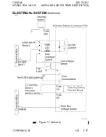
ELECTRICAL SYSTEM
(Continued)
LOW VOLTAGE ANNUNCIATION
(Continued)
ALT FIELD circuit breaker may open on occasion during normal
engine starts due to transient overvoltages. Provided that normal
alternator output is resumed after the ALT FIELD circuit breaker is
reset, these occurrences are considered nuisance events. If the
ALT FIELD circuit breaker opens after reset, do not close again.
Repeated occurrences indicate a problem with the electrical system
that must be corrected by a qualified maintenance technician before
flight.
CIRCUIT BREAKERS AND FUSES
Individual system circuit breakers are found on the circuit breaker
panel below the pilot's control wheel. All circuit breakers are
"pullable" for electrical load management. Using a "pullable"
circuit breaker as a switch is discouraged since the practice will
decrease the life of the circuit breaker.
The Power Distribution Module uses three circuit breakers for the
electrical bus feeders. A "fast blow" automotive type fuse is used
at the Standby Battery. The Standby Battery current shunt circuit
uses two field replaceable fuses located on the Standby Battery
Controller printed circuit board.
Most Garmin G1000 equipment has internal non-field replaceable
fuses. Equipment must be returned to Garmin by an approved
service station for replacement.
EXTERNAL POWER RECEPTACLE
A external power receptacle is integral to the power distribution
module and allows the use of an external power source for cold
weather starting or for lengthy maintenance work on electrical and
avionics equipment. The receptacle is located on the left side of the
cowl near the firewall. Access to the receptacle is gained by
opening the receptacle door.
(Continued Next Page)
7-52 U.S.
172SPHAUS-00
Содержание 172S Skyhawk SP NAV III 2005
Страница 4: ......
Страница 6: ......
Страница 8: ......
Страница 10: ......
Страница 24: ...SECTION 1 CESSNA GENERAL MODEL 172S NAV III Figure 1 2 Weight Conversions Sheet 2 1 16 U S 172SPHAUS 00 ...
Страница 26: ...SECTION 1 CESSNA GENERAL MODEL 172S NAV III Figure 1 3 Length Conversions Sheet 2 1 18 U S 172SPHAUS 00 ...
Страница 28: ...SECTION 1 CESSNA GENERAL MODEL 172S NAV III Figure 1 4 Length Conversions Sheet 2 1 20 U S 172SPHAUS 00 ...
Страница 29: ...CESSNA SECTION 1 MODEL 172S NAV III GENERAL Figure 1 5 Distance Conversions 172SPHAUS 00 U S 1 21 ...
Страница 31: ...CESSNA SECTION 1 MODEL 172S NAV III GENERAL Figure 1 6 Volume Conversions Sheet 2 172SPHAUS 00 U S 1 23 ...
Страница 32: ...SECTION 1 CESSNA GENERAL MODEL 172S NAV III Figure 1 6 Volume Conversions Sheet 3 1 24 U S 172SPHAUS 00 ...
Страница 33: ...CESSNA SECTION 1 MODEL 172S NAV III GENERAL Figure 1 7 Temperature Conversions 172SPHAUS 00 U S 1 25 ...
Страница 35: ...CESSNA SECTION 1 MODEL 172S NAV III GENERAL Figure 1 9 Volume to Weight Conversion 172SPHAUS 00 U S 1 27 ...
Страница 36: ...SECTION 1 CESSNA GENERAL MODEL 172S NAV III Figure 1 10 Quick Conversions 1 28 U S 172SPHAUS 00 ...
Страница 38: ......
Страница 60: ......
Страница 64: ......
Страница 83: ...CESSNA SECTION 3 MODEL 172S NAV III EMERGENCY PROCEDURES MAXIMUM GLIDE Figure 3 1 I172SPHAUS 01 U S 3 23 ...
Страница 100: ......
Страница 148: ......
Страница 157: ...CESSNA SECTION 5 MODEL 172S NAV III PERFORMANCE Figure 5 2 Temperature Conversion Chart 172SPHAUS 00 U S 5 11 ...
Страница 170: ......
Страница 172: ......
Страница 194: ......
Страница 198: ......
Страница 294: ......
Страница 296: ......
Страница 320: ...SECTION 9 SUPPLEMENTS CESSNA SUPPLEMENT 3 MODEL 172S NAV III Figure S3 1 FAA APPROVED S3 8 U S 172SPHAUS S3 00 ...
Страница 366: ......
Страница 408: ......
Страница 422: ......


