


Chapter 6 - Parameter Description
6-26
Interlock 1, 2, 3 & 4-
This function is used for
MMC operation to disable and remove any
auxiliary motor from the normal start/stop
sequence. When MMC is enabled and M1, M2, M3
or M4 is set to Interlock and activated, the
corresponding AUX relay output will be disabled.
Reset-
When this input is activated, the VFD fault
will be reset. Some critical faults can only be reset
by cycling power to VFD.
BX-
If this input is activated, the VFD will
activate an emergency stop mode without
deceleration. There are two ways to return to
normal control mode based on I/O-30 setting:
automatic or by VFD reset. This is not a fault
and it will not be saved in the fault history.
JOG-
When Jog input and FX or RX inputs are
activated in V/F control mode , the VFD starts
forward or reverse with jog speed reference set in
DRV-16.
FX-
If SET-09 is set to Remote-1 or Remote-2
control mode and this input is activated, the VFD
will start in forward direction.
RX-
If SET-09 is set to Remote-1 or Remote-2
control mode and this input is activated, the VFD
will start in reverse direction.
ANA_Change-
If SET-10 is set to V1+I speed
control mode and this input is activated, the VFD
will switch from V1 0-10VDC input to I 4-20mA
input. When input is deactivated, the control
switches back to V1 input.
Ext.PID Run-
When this input is activated, the
External PID control function begins operation
even without VFD run command.
Up/Dwn Clr-
When any two inputs are set to UP
and DOWN speed control mode and this input is
activated, the adjusted speed reference will be reset
to 0.
Jog_FX and Jog_RX-
When Jog-FX input is
activated, the VFD starts forward in jog mode with
jog speed set in DRV-16. When Jog-RX input is
activated, the VFD starts reverse in jog mode with
jog speed set in DRV-16. When both inputs are
activated, VFD will stop.
Damper SW-
When any input is set to Damper
Switch and VFD receives run command, the
selected Damper AUX Relay will be activated to
start a damper actuator and VFD will start the
motor when the Damper Switch input closes.
Smoke Purge-
When this input is activated, the
VFD will start and run the motor at maximum
frequency limit with most of the motor and VFD
protections disabled.
$ ) 4+
- $! '
'
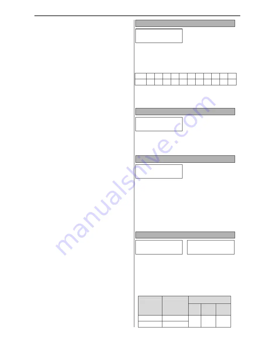
The I/O-28 parameter shows real time inputs status
in 0/1= OFF/ON bit format. Each digit (bit)
represents one digital input status starting from the
right to the left.
Input P6 P5 P4 M8 M7 M6 M5 M4 M3 M2 M1
Bit
10
9
8
7
6
5
4
3
2
1
0
This parameter is very useful for control trouble-
shooting.
$ ) 5+
" !-
> "
- $! '
The I/O-29 parameter sets the filtering time for
digital inputs. The default value is sufficient for
electrical noise filtering in most of the applications.
$ ).*+ ;?
>
There are to ways to reset BX Emergency Stop
mode: Manual and Automatic.
If I/O-30 is set to No and BX input is activated
momentarily, the VFD will stay in Emergency Stop
mode until VFD is reset.
If I/O-30 is set to Yes and BX input is activated, the
VFD will stop in Emergency Stop mode and resets
automatically when BX input is deactivated.
$ )7*A0.+ %
A3
These parameters provide up to seven different
Accel/Decel time settings for custom speed control
curve. When any three digital inputs are
programmed for XCEL-L, M and H, Accel/Decel
time will be determined by binary combination of
these inputs. (0= Off and 1= On)
Parameter
Code
Accel/Decel
Time #
XCEL
H
(M3)
M
(M2)
L
(M1)
SET-11
Accel Time-0
0
0
0
SET-12
Decel Time-0
I/O In Status
28 00001000000
I/O DI Filter
29 15 ms
I/O BX SelfReset
30 Yes
I/O Acc Time-1
50 20.0 sec
I/O Dec Time-1
51 20.0 sec
Содержание CI-007-P2
Страница 23: ......
Страница 107: ......
Страница 109: ...Chapter 6 Parameter Description 7 2 7 3 PID control Sleep mode with Sleep Pressure Boost function diagram...
Страница 110: ...Chapter 6 Parameter Description 7 4 PID control with Pipe Broken function diagram...
Страница 111: ...Chapter 6 Parameter Description 7 4 7 5 PID control with Pre PID function diagram...
Страница 112: ...Chapter 6 Parameter Description 7 5 7 6 PID Control Setting Notes...
Страница 113: ......
Страница 126: ...Chapter 9 Options 9 7 Conduit box for 030 040HP VFD Conduit box for 050 075HP VFD Conduit box for 100 125HP VFD...


