


Chapter 5 – Parameter List
4-9
Keypad-1. The frequency in DRV-00 parameter is the 1
st
Speed and the 2
nd
Speed is activated by M1 input
and can be adjusted in parameter DRV-01.
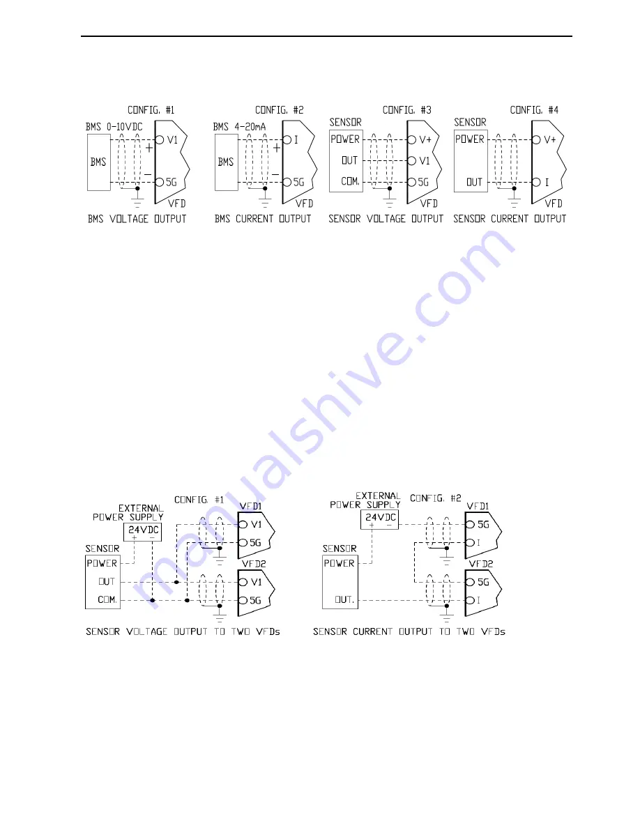
4.4.2 Examples of analog speed control configurations
The 4.4.2 picture shows four most common VFD speed control configurations.
Config. #1
shows VFD with speed controlled by remote 0-10VDC signal from BMS, PLC or any other
controller. The VFD parameter SET-10 is set to V1 mode. During normal operation if an electrical noise
level in analog signal is too high, VFD output can stay at maximum frequency for some time when speed
reference signal is decreasing. Increase a filtering time setting in parameter I/O-01 up to 500mS.
Config. #2
shows VFD with speed controlled by remote 4-20mA signal from BMS, PLC or any other
controller. The VFD parameter SET-10 is set to I mode. During normal operation if a noise level in analog
signal is too high, VFD output can stay at maximum frequency for some time when speed reference signal is
decreasing. Increase a filtering time setting in parameter I/O-06 up to 500mS.
Config. #3
shows VFD with automatic speed control by internal PID and 0-10VDC feedback signal from
pressure, temperature or any other transducer. The VFD PID parameter SET-20 is enabled and SET-21 is set
to V1 mode. Increasing a filtering time setting in parameter I/O-01, when PID control is enabled, can
decrease a control accuracy.
Config. #4
shows VFD with automatic speed control by internal PID and 4-20mA feedback signal from
pressure, temperature or any other transducer. The VFD PID parameter SET-20 is enabled and SET-21 is set
to I mode. Increasing a filtering time setting in parameter I/O-06, when PID control is enabled, can decrease
a control accuracy.
Two VFDs wired to one transducer.
Config. #1
above shows two VFDs with automatic speed controls by internal PIDs and 0-10VDC feedback
signal from one pressure, temperature or any other transducer with external 24VDC power source. The
sensor with 0-10VDC output can be paralleled with multiple VFDs. Losing the power on one VFD does not
affect the PID operation of another VFD with transducer feedback. Use CM instead of 5G for VFDs 50HP
and above.
Config. #2
above shows two VFDs with automatic speed controls by internal PIDs and 4-20mA feedback
signal from one pressure, temperature or any other transducer with external 24VDC power source. The
sensor with 4-20mA output is usually limited by 650 load impedance. The VFD input impedance is 249
thus only two VFDs can be connected in series with one transducer. Losing the power on one VFD does not
affect the PID operation of another VFD with transducer feedback. Use CM instead of 5G for VFDs 50HP
and above.
Содержание CI-007-P2
Страница 23: ......
Страница 107: ......
Страница 109: ...Chapter 6 Parameter Description 7 2 7 3 PID control Sleep mode with Sleep Pressure Boost function diagram...
Страница 110: ...Chapter 6 Parameter Description 7 4 PID control with Pipe Broken function diagram...
Страница 111: ...Chapter 6 Parameter Description 7 4 7 5 PID control with Pre PID function diagram...
Страница 112: ...Chapter 6 Parameter Description 7 5 7 6 PID Control Setting Notes...
Страница 113: ......
Страница 126: ...Chapter 9 Options 9 7 Conduit box for 030 040HP VFD Conduit box for 050 075HP VFD Conduit box for 100 125HP VFD...


