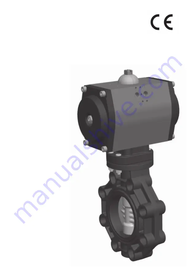
EXTREME
BUTTERFLY VALVES
Pneumatic actuator
INSTALLATION ANDMAINTENANCE MANUAL
PVC-U (EPDM/FPM)
CPVC (EPDM/FPM)
PPH (EPDM/FPM)
PVDF (EPDM/FPM)
ABS (EPDM/FPM)
0045
Страница 1: ...EXTREME BUTTERFLY VALVES Pneumatic actuator INSTALLATION AND MAINTENANCE MANUAL PVC U EPDM FPM CPVC EPDM FPM PPH EPDM FPM PVDF EPDM FPM ABS EPDM FPM 0045...
Страница 2: ...teriales termopl sticos Meets the requirements established by the European Union for PRESSURE EQUIPMENT ac cording to Directive 2014 68 UE PED category II module A2 in accordance with the harmo nized...
Страница 3: ...3 ENGLISH PAGE 04 ESPA OL PAGE 12 FRAN AIS PAGE 20 PORTUGU S PAGE 28 ITALIANO PAGE 36 DEUTSCH PAGE 44...
Страница 4: ...at the factory using ageing tests specified in the standard Correct installation and handling of the valve as well as adherence to the maximum pressure and temperature conditions specified in this man...
Страница 5: ...g bush AISI 304 1 3 Mounting clamp PP GR 1 4 Pneumatic actuator Anodised Aluminium PA 1 5 Limit switch box OPTIONAL different models available 1 6 Solenoid valve OPTIONAL different models available 1...
Страница 6: ...e carga bar Pressure loss bar Caudal l min Flow l min 0 10 20 30 40 50 60 70 80 90 100 0 10 20 30 40 50 60 70 80 90 100 Kv valve opening apertura Flow valve opening Caudal Apertura DN65 DN80 DN100 DN1...
Страница 7: ...114 384 427 12 Fig 3 T4 1 mm See the actuator and limit switch manuals to check the dimensions D E and G Fig 4 DN ISO FLANGE SQUARE mm 40 F07 14 17 65 F07 14 17 80 F07 14 17 100 F07 14 17 125 F07 17...
Страница 8: ...tightening sequence of the screws on the flanges Fig 6 and the maximum tightening torque All screws must be used in the flange in order to ensure proper operation of the valve The PP PE sockets for bu...
Страница 9: ...e position The valve is opened and closed by applying air pressure to the corresponding control connections A 5 2 solenoid valve is required to carry out the action In the case a normally closed monos...
Страница 10: ...the cap 7 and remove the screw 12 Tap on the shaft 6 with a rubber mallet until the bearing 4 is exposed from the bottom Fig 11 Once the bearing is out remove the shaft 6 turn it and re insert it Fig...
Страница 11: ...he sockets Misalignment between sockets and valve Disassemble the valve and reas semble with concentric alignment observe the correct tightening sequence and torque Flange screws not tight enough Tigh...
Страница 12: ...6 sta ha sido verificada en f brica con pruebas de envejecimiento especificadas en la norma La correcta instalaci n y manejo de la v lvula as como el cumplimiento de las condiciones de presi n m xima...
Страница 13: ...nexi n Aluminio phosphochromado DN65 DN150 AISI 304 DN200 DN300 1 3 Brida de fijaci n PP GR 1 4 Actuador neum tico Anodised Aluminium PA 1 5 Limit switch box OPTIONAL different models available 1 6 V...
Страница 14: ...ng apertura Flow valve opening Caudal Apertura DN65 DN80 DN100 DN125 DN150 DN200 DN250 DN300 Kv apertura G 3 2 Gr fico p rdidas de carga G 3 3 Tabla p rdidas de carga T 3 1 D DN Kv l min Cv GPM 63 75...
Страница 15: ...anual del actuador para las dimensiones D E y G Fig 4 Dimensiones de acople del actuador T 4 2 Valve design Flanged dimensions Valve connections Other connections Actuator coupling ISO 16136 2005 EN 5...
Страница 16: ...te que se usen todos los tornillos en la brida para asegurar un mejor funcionamiento de la v lvula Los manguitos en PP PE para soldadura a tope deben ser chaflanados tal como indica el gr fico Fig 7 y...
Страница 17: ...nes de control Para la instalaci n es requerida una v lvula de solenoide 5 2 En el caso de la instalaci n de una v lvula solenoide monoestable normalmente cerrada la se al el ctrica deber ser mantenid...
Страница 18: ...el tornillo 12 Golpear el eje 6 con una maza de goma hasta que el casquillo 4 aparezca por la parte inferior de la v lvula Fig 11 Una vez haya salido el casquillo retirar el eje 6 girarlo y volver a...
Страница 19: ...nguitos y v lvula Desmontar la v lvula y volver a montar con alineamiento concentrico observar el apriete y secuanecia correctos Par insuficiente de la brida Apretar las bridas omo indica la tabla T5...
Страница 20: ...aux tests de vieillissement prescrits par ladite norme L installation et la manipulation ad quates du robinet ainsi que le respect des conditions maximales de temp rature et de pression indiqu es dans...
Страница 21: ...raccorde ment Phosphochromate Aluminium DN65 DN150 AISI 304 DN200 DN300 1 3 Bride de fixation PP GR 1 4 Actionneur Anodised Aluminium PA 1 5 Bo tier fin de course OPTIONAL different models available 1...
Страница 22: ...min Flow l min 0 10 20 30 40 50 60 70 80 90 100 0 10 20 30 40 50 60 70 80 90 100 Kv valve opening apertura Flow valve opening Caudal Apertura DN65 DN80 DN100 DN125 DN150 DN200 DN250 DN300 Diagramme p...
Страница 23: ...onneur et de l interrupteur de fin de course afin de v rifier les dimensions D E et G Fig 4 Dimensions fixation T 4 2 Valve design Flanged dimensions Valve connections Other connections Actuator coupl...
Страница 24: ...e des vis sur les brides Fig 6 et le couple de serrage maximal Toutes les vis doivent tre utilis es dans les brides afin d assurer un bon fonctionnement de la vanne Les raccordements PP PE pour soudag...
Страница 25: ...de commandes correspondantes Un robinet sol no de de 5 2 est n cessaire afin d ex cuter cette action Si un robinet sol no de monostable normalement ferm e est install le signal lectrique doit tre main...
Страница 26: ...t en caoutchouc jusqu ce que le roulement 4 soit visible sur la partie inf rieure Fig 11 Une fois le roulement l ext rieur retirez le manche 6 tournez le puis r ins rez le Fig 12 partir de la partie i...
Страница 27: ...montez la vanne et assemblez de nou veau en suivant un alignement concentrique respectez correctement la s quence de serrage et de couplage Vis d accouplement pas assez serr s Serrez les brides comme...
Страница 28: ...im como o cumprimento das condi es de press o m xima e temperatura especificadas neste manual s o essenciais para preservar a vida til da v lvula O l quido conduzido deve ser compat vel com os materia...
Страница 29: ...304 DN200 DN300 1 3 Flange de uni o PP GR 1 4 Actuador pneumatico Anodised Aluminium PA 1 5 Fins de curso OPTIONAL different models available 1 6 V lvula solenoide OPTIONAL different models available...
Страница 30: ...0 80 90 100 Kv valve opening apertura Flow valve opening Caudal Apertura DN65 DN80 DN100 DN125 DN150 DN200 DN250 DN300 Diagrama de press o temperatura G 3 1 Kv opening G 3 2 Diagrama das perdas de car...
Страница 31: ...nsulte o manual do actuador para as dimens es D E e G Fig 4 Dimens es uni o T 4 2 Valve design Flanged dimensions Valve connections Other connections Actuator coupling ISO 16136 2005 EN 558 1 ANSI B16...
Страница 32: ...dos os parafusos sejam usados no flange para assegurar um melhor funcionamento da v lvula As bra adeiras em PP PE para soldar a extremidade devem ser cortadas em forma de meia lua como mostrado no gr...
Страница 33: ...ala o necess ria v lvula solen ide 5 2 No caso de instala o de uma v lvula solenoide monoest vel normalmente fechada o sinal el ctrico dever ser mantido durante o tempo que pretender manter a v lvula...
Страница 34: ...ampa 7 e parafuso 12 Martele o eixo 6 com um martelo de borracha at que o casquilho 4 apare a pela parte inferior da v lvula Fig 11 Uma vez que o casquilho tenha sa do retirar o eixo 6 gir lo e voltar...
Страница 35: ...inhamento entre as bra adei ras e a v lvula Desmontar a v lvula e voltar a montar com um alinhamento conc ntrico ob serve o aperto e sequ ncia correctos Par insuficiente do flange Serrez les brides co...
Страница 36: ...La corretta installazione e uso della valvola nonch il rispetto dei requisiti massimi di pressione e temperatura specificati nel presente manuale sono fondamentali per la salvaguardia della vita utile...
Страница 37: ...Phosphochromate Aluminium DN65 DN150 AISI 304 DN200 DN300 1 3 Torretta di sostegno PP GR 1 4 Attuatore pneumatico Anodised Aluminium PA 1 5 Box di fine corsa OPTIONAL different models available 1 6 Va...
Страница 38: ...50 60 70 80 90 100 Kv valve opening apertura Flow valve opening Caudal Apertura DN65 DN80 DN100 DN125 DN150 DN200 DN250 DN300 Diagramma pressione temperatura G 3 1 Kv opening G 3 2 Diagramma delle pe...
Страница 39: ...dere il manuale dell attuatore per le dimensioni D E e G Fig 4 Dimensioni unioni T 4 2 Valve design Flanged dimensions Valve connections Other connections Actuator coupling ISO 16136 2005 EN 558 1 ANS...
Страница 40: ...ggio E importante utilizzare tutte le viti della flangia per assicurarsi che la valvola funzioni nel miglior modo possibile I manicotti in PP PE per saldatura di testa devono essere smussati come indi...
Страница 41: ...plicando aria sotto pressione ai collegamenti di controllo corrispondenti Per l installazione necessaria una valvola solenoide 5 2 Nel caso dell installazione di una valvola solenoide mono stabile nor...
Страница 42: ...l tappo 7 e la vite 12 Colpire l asse 6 con un martello di gomma fino all apparizione del guscio 4 dalla parte inferiore della valvola Fig 11 Una volta fuoriuscito il guscio ritirare l asse 6 girarlo...
Страница 43: ...alvola Smontare la valvola e rimontarla con allineamento concentrico attenersi al ser raggio e alla sequenza corretti Coppia della flangia insufficiente Serrare le flange come indicato nella tabella T...
Страница 44: ...und Temperaturbedingungen die in dieser Anleitung angef hrt sind sind entscheidend um die Lebensdauer des Ventils zu erhalten Die gef hrte Fl ssigkeit muss mit allen Materialien des Ventils kompatibel...
Страница 45: ...Kupplungsst ck Phosphochromate Aluminium DN65 DN150 AISI 304 DN200 DN300 1 3 Zwischenst ck PP GR 1 4 Stellantrieb Anodised Aluminium PA 1 5 Endschaltergeh use OPTIONAL different models available 1 6...
Страница 46: ...100 Kv valve opening apertura Flow valve opening Caudal Apertura DN65 DN80 DN100 DN125 DN150 DN200 DN250 DN300 Druck Temperatur Diagramm G 3 1 Kv opening G 3 2 Druckverlus Diagramm G 3 3 Druckverlust...
Страница 47: ...Siehe Betriebsanleitung des Antriebs f r die Abmessungen D E und G Fig 4 ABMESSUNGEN T 4 2 Valve design Flanged dimensions Valve connections Other connections Actuator coupling ISO 16136 2005 EN 558 1...
Страница 48: ...r Schrauben Abbildung 6 sowie das maximale Anzugsmoment Es ist wichtig dass alle Schrauben des Flasch genutzt werden um sicherzustellen dass das Ventil ordnungsgem funktioniert Die PP PE Muffen f r da...
Страница 49: ...fnet oder schlie t sich wenn Luftdruck auf die entsprechenden Steueranschl sse wirkt F r die Installation wird ein 5 2 Wege Magnetventil ben tigt Wenn ein monostabiles Magnetventil das normalerweise g...
Страница 50: ...Gummihammer auf die Welle 6 bis das Lager 4 auf der Unterseite des Ventils sichtbar wird Abbildung 11 Wenn das Lager herausgenommen wurde entfernen sie die Welle 6 drehen Sie sie und setzen Sie sie e...
Страница 51: ...Das Ventil ausbauen und mit einer konzentrischen Ausrichtung erneut einbauen achten Sie auf das korrekte Anzugsmoment und die Reihenfolge Flanschschrauben zu locker Flansch gem Tabelle T5 1 festziehe...
Страница 52: ...Av Ram n Ciurans 40 PI Congost P6 La Garriga BCN Spain Tel 34 93 870 42 08 www cepex com cepex cepex com CODE C584075MNXT VERSION 2 1 DATE 17 10 2019 COPYRIGHT CEPEX S A U ALL RIGHTS RESERVED...