5
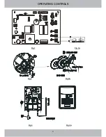
1.
INFRARED SAFETY BEAM ENABLE DIP SWITCH. (
2.
AUTO CLOSE ENABLE DIP SWITCH.
3.
AUTO CLOSE DELAY DIP SWITCHES
4.
SAME AS ABOVE
5
CODE BUTTON
NOVA VOYAGER
6
CLOSE DIRECTION SAFETY OBSTRUCTION FORCE ADJUSTMENT SCREW
7.
OPEN DIRECTION SAFETY OBSTRUCTION FORCE ADJUSTMENT SCREW
8.
CODE LAMP
9.
OUTPUT TERMINALS
10.
RADIO RECEIVER
NOVA VOYAGER
11
AUTO COURTESY LIGHT
12.
JUMPER PLUG (J8)
15
OPEN LIMIT CAM
14.
CLOSE LIMIT CAM
16
OPEN LIMIT MICRO SWITCH
16.
CLOSE LIMIT MICRO SWITCH
17.
ENGAGE/DISENGAGE LEVER
18.
EXTERNAL PUSH BUTTON
19.
POSITIVE BATTERY CABLE
20
PLUG PACK BATTERY CHARGER
refer Sec.18 )
(refer Sec.21)
are used to adjust the time to auto close. (refer Sec.21)
used for storing or erasing transmitter security code (refer Sec.15) (Does not apply if kit
supplied with
receiver)
is used to adjust the
Safety Obstruction Force value in the Open Direction (refer Sec.11 & 13)
is used to adjust the Safety
Obstruction Force value in the Close Direction (refer Sec.12 & 14)
signals stages of transmitter code learning process (refer Sec.15)
for connection of infrared safety beams or remote mounted push button. (refer
Sec.17, 18 & 22)
processes the signal from the hand held transmitter. (Does not apply if kit supplied with
receiver)
is activated automatically each time the opener commences an open or close
cycle and remains on for approx 3 minutes.
switches power supply for use with either one of Safety Beams or external Receiver.
(refer Sec.18)
is used to adjust the door fully open position. (refer Sec.7 & 10)
is used to adjust the door fully closed position. (refer Sec.8 & 10)
is used to stop door when it reaches the fully open position.
is used to stop the door once it reaches the fully closed position.
engages/disengages opener from the door. (refer Sec.4)
alternatively opens, closes or stops the door when activated.
.
.
.
.
.
.
OPERATING CONTROLS
Open force setting
Confirmation LED
Learn
Close force setting
Operate Button
Содержание CS32 RDO
Страница 1: ...INSTALLATION MANUAL...
Страница 5: ...OPERATING CONTROLS Fig 1 Fig 1A Fig 2 Fig 2A Fig 3 Fig 3A 4 OPERATING CONTROLS...
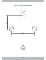
Страница 19: ...18 CONTROL BOX MOUNTING TEMPLATE 80...
Страница 21: ......

