12.
13.
14
Safety Obstruction Force Adjustment – Open Direction
Safety Obstruction Force Testing – Close Direction
Safety Obstruction Force Testing – Open Direction
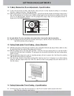
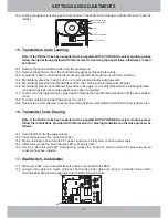
12.1 Locate the Open force setting (UP) thumb screw and turn it to the maximum setting in a clockwise
direction. (Upper of 2 screws – refer figure below)
12.2 With the garage door in the fully CLOSED position - press the red button located on the face of the Control
Box. As the garage door commences to OPEN, slowly begin to turn the Open force setting (UP) thumb
screw in an anti-clockwise direction until the garage door stops. Now turn the adjustment back 10
degrees in a CLOCKWISE direction.
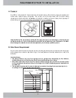
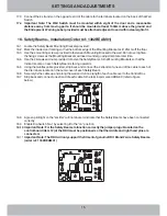
13.1 With the garage door in the fully open position, place a length of timber measuring 100mm x 50mm on the
floor directly under the middle of the garage door. (Fig.16)
13.2 With the garage door in the fully open position - close the door by pressing the red “operate” button
located on the front of the Control Box. The garage door should strike the timber and then automatically
start to re-open.
13.3 If the garage door does not re-open or requires excessive force to re-open, then the Close force setting
(DN) thumb will need to be re-adjusted.
13.4 Turn the Close direction Close force setting (DN) thumb screw 5 to 10 degrees in an anti-clockwise
direction and then repeat steps 13.2 and 13.3 until such time as the garage door will reverse when it
hits the timber.
12.3 Important Note: The door must stop and reverse before it reaches the fully Open position.
12.4 Test the adjustment by pressing the red “operate” button again. This time the door should reach the
fully OPEN position without stopping.
.
14.1 With the garage door in the fully closed position – press the red “operate” button located on the front
face of the Control Box to open the door.
Fig 16
13
SETTINGS AND ADJUSTMENTS
Open force setting
Confirmation LED
Learn
Close force setting
Operate Button
Содержание CS32 RDO
Страница 1: ...INSTALLATION MANUAL...
Страница 5: ...OPERATING CONTROLS Fig 1 Fig 1A Fig 2 Fig 2A Fig 3 Fig 3A 4 OPERATING CONTROLS...
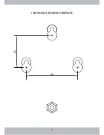
Страница 19: ...18 CONTROL BOX MOUNTING TEMPLATE 80...
Страница 21: ......

