19.
20.
21.
Safety Beams - Alignment
Safety Beam – Function Testing
Auto Close Mode
22. Output Terminals
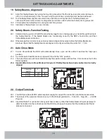
19.1
Align the 2 Safety Beams (by turning the mounting bracket) so that their lenses are aimed directly at each
other. A red indicator lamp on the “receiver” will glow solid once correct alignment has been achieved.
19.2
Test the Safety Beam alignment several times, each time ensuring that when the Safety Beams are
obstructed the red indicator lamp is extinguished, and when unobstructed the indicator lamp glows solid.
19.3
Firmly tighten the Safety Beam mounting bracket fixing screws.
19.4
Installation of Safety Beams is now complete.
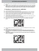
20.1
20.2
21.1
21.2
21.3
Initiate a closing cycle on the RDO and as the Garage Door is closing pass your hand through the line of
the Safety Beams. If the Safety Beams are functioning correctly the RDO should stop and then
immediately reverse direction.
If the Garage Door commences a close cycle but stops and reverses before the Safety Beams are
blocked, check that the Safety Beams are aligned correctly as outlined in points 18.1 ~ 18.3.
In Auto Close Mode the RDO will automatically close a pre set time after it reaches the fully open
position.
To enable Auto Close Mode move dip switch No.2 to the “ON” position.
The Auto Close pre set time is determined by the position of dip switches Nos. 3 & 4 and is set out in the
following table:
22.1
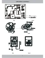
The RDO provides a 24VDC external power supply to support the connection of external accessories.
22.2
The values of the output terminals is set out in the following table: 9A ~ Com, 9B ~ Neg, 9C ~ +24VDC
(Fig.xxx).
22.3
Important Note: For connection of any external accessory other than Safety Beams the jumper plug J8
(Item12) located on the control board of the RDO must be positioned so that the middle and left hand
pins are connected.
21.4
Important Note: Auto Close Mode will only work if Safety Beams have been enabled and correctly
aligned
16
SETTINGS AND ADJUSTMENTS
Time/Dip
switch
15 sec
30 sec
3
4
OFF
OFF
ON
ON
1
2
3
4
5
6
7
8
9
11
12
9
9
10
A
B
C
1
2
3
4
5
6
7
8
9
11
12
9
9
10
A
B
C
Содержание CS32 RDO
Страница 1: ...INSTALLATION MANUAL...
Страница 5: ...OPERATING CONTROLS Fig 1 Fig 1A Fig 2 Fig 2A Fig 3 Fig 3A 4 OPERATING CONTROLS...
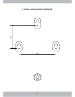
Страница 19: ...18 CONTROL BOX MOUNTING TEMPLATE 80...
Страница 21: ......


