


18
17
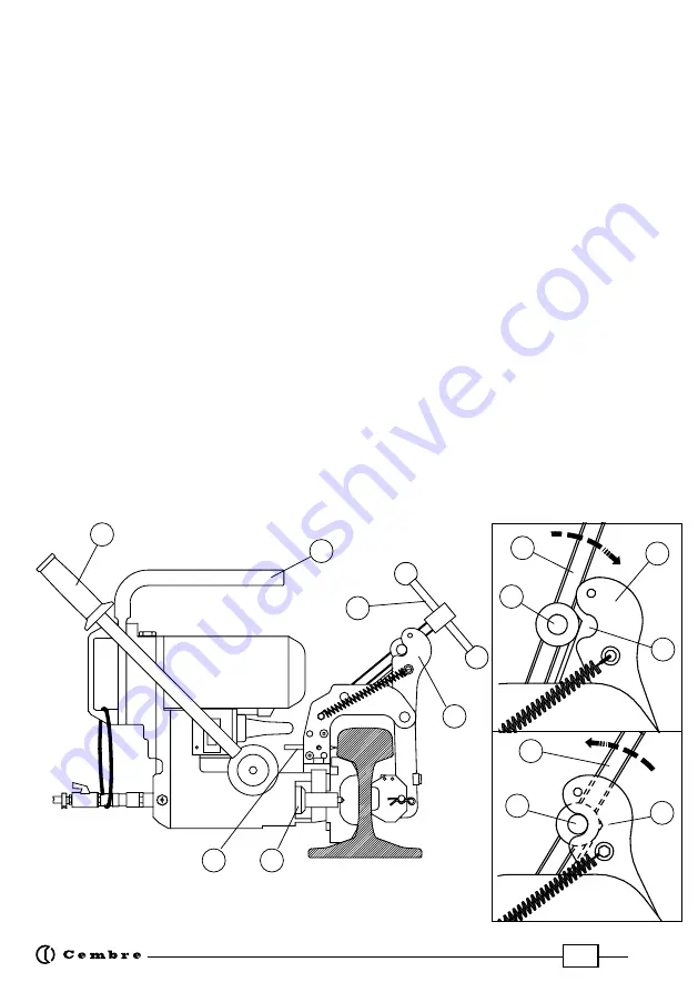
7.4) Clamping to the rail web
(Ref. to Fig. 16)
The drill has a rapid rail engagement/release mechanism and specially shaped positioning
templates for each rail type which facilitate precise and certain location of the part to be drilled.
To fully exploit the special features of the engagement device, we recommend calibrating it to
the rail type to be drilled as follows:
7.4.1)
Withdraw the spindle shaft (07) completely by means of the lever (36).
7.4.2)
Insert the threaded bush (39) of screw (11) into its seat (A) in the mobile arm (17) (see
detail in Fig. 17); use the hand-wheel (12) to completely open the mobile arm.
7.4.3)
Place the drill on the track at the point to be drilled and
clamp it by tightening the hand-
wheel fully down (12)
: the positioning template will automatically position the cutter or drill bit
in line with the designated axis; if precise positioning is necessary to the longitudinal track axis,
use the reference pin (01).
7.4.4)
For rapid drill release, simply back-off the hand-wheel (12) by approximately two com-
plete turns, and while supporting the drill by its grip (09), pull the hand-wheel towards you. The
threaded bush (39) will disengage the seat (A) in the mobile arm (17) which will open automati-
cally, freeing the drill.
In this way, the operator can rapidly remove the machine from the track in case of danger, or
move on to drill another hole.
Thus, the next track engagement operation will be considerably simplified:
after positioning the drill at the point to be drilled, simply push the hand-wheel forwards so that
the threaded bush engages the seat (A) of the mobile arm. Now, a few turns on the hand-wheel
will be sufficient to engage the drill correctly on the track.
FIG. 16 – POSITIONING THE DRILL
(eg on UIC60 rail with MPAF UIC60 template)
39
11
17
A
17
39
11
12
36
17
07
01
09


