background image

www.cellarcool.com | Page 23

 WM & FD Twin

2. Using a drill with a 3/16” bit, drill four holes in the drywall for the screws. Insert the four (4) provided drywall anchors 

into the drywall, then tap them in with a hammer until they are flush with the wall. 

WALL MOUNT BRACKET INSTALLATION, CONTINUED

3. Place bracket against wall, aligning screw holes with drywall anchors. Insert the four supplied Phillips-head screws 

into the drywall anchors. Tighten the screws to secure the bracket to the wall. 

Содержание 9000 TWIN-S

Страница 1: ...WALL MOUNTED FULLY DUCTED 9000 TWIN S TECHNICIAN S MANUAL ...

Страница 2: ...s not responsible for printing or clerical errors CellarCool reserves the right to make corrections or improvements to the information provided and to the related hardware at any time without notice Vinothèque and CellarCool are registered trademarks and ECE is a trademark of CellarCool All rights reserved Mention of third party products is for informational purposes only and constitutes neither a...

Страница 3: ...r Units 16 Installing the Fully Ducted Evaporator Units 17 Ducting Overview 18 Ducting Configurations 19 Drain Line 20 Liquid Measuring Thermostat Bottle Probe 21 Remote Display Installation 22 Wiring Diagrams WM FD 9000 Twin S 28 WM FD 9000 Twin S Master Evaporator 29 WM FD 9000 Twin S Slave Evaporator 30 WM FD 9000 Twin S Condensing Unit 31 Copeland Cold Weather Start Kit 32 Preparing the Conden...

Страница 4: ...is also vital to establish a proper care and maintenance schedule Please read and review this manual carefully and keep it for future reference What is the CellarCool Cooling System The CellarCool cooling system is a specialized refrigeration system designed for one purpose only to maintain the optimal temperature and humidity levels conducive to the proper storage and aging of fine wines This sys...

Страница 5: ...GUIDE TXV Adjustments A A TXV adjustment may be necessary based on ambient temperatures in the cellar and at the condensing unit B Adjust the TXV until the superheat measured at the suction line service valve is 20 30 F C Under normal operation with the wine cellar at 55 F and the ambient temperature at 85 F the low side pressure should be between 28 32 PSI and the high side should be between 160 ...

Страница 6: ... system is intended for use in properly designed and constructed wine cellars Hire a professional wine storage consultant with a valid contractor s license to build your wine cellar 6 CellarCool requires that all split systems be installed by a certified HVAC R technician only NATE or equivalent is recommended 7 It is vital that the units be set apart and oriented so that the return air from one u...

Страница 7: ...vacuated during this time NOTE CellarCool units are manufactured in the USA and tested prior to shipment Review the packing slip to verify contents Check the model number to ensure it is correct Check that all factory options ordered are listed If any items listed on the packing slip do not match your order information contact CellarCool Customer Service immediately Documentation bag master WM FD ...

Страница 8: ...HROUGH THE WALL Option 1 Knockout for wiring Knockout for wiring Knockout for drain line Line set knockout Mounting keyholes 4 Line set knockout Knockout for drain line Wall Mounted Front Side View Wall Mounted Rear Side View REAR VIEW Filter grille Evaporator unit Return air Supply air ...

Страница 9: ...ly air Fully Ducted Front Side View INSIDE CELLAR Option 2 THROUGH THE WALL Option 1 Knockout for wiring Knockout for wiring Knockout for drain line Line set knockout Mounting keyholes 4 Line set knockout Knockout for drain line Fully Ducted Rear Side View REAR VIEW ...

Страница 10: ... Amps Evaporator 1 running amp per unit Compressor LRA 35 RLA 6 5 Evaporator 1 running amp per unit Compressor LRA 35 RLA 6 5 Line Set Liquid line 3 8 suction line 3 4 less than 50 ft 7 8 greater than 50 ft Drain Line 1 2 ID clear plastic tubing not provided Installation Evaporator units are installed in the cellar Thermostat Advanced digital display 50 ft cable liquid temperature measuring bottle...

Страница 11: ... per unit Compressor LRA 35 RLA 6 5 Evaporator 1 running amp per unit Compressor LRA 35 RLA 6 5 Line Set Liquid line 3 8 suction line 3 4 less than 50 ft 7 8 greater than 50 ft Duct Size 8 supply 10 return x2 Drain Line 1 2 ID clear plastic tubing not included Installation Evaporator units can be installed up to 25 ducted feet away Thermostat Advanced digital display connected to master unit with ...

Страница 12: ... Cooled Condensing Unit Dimensions 24 L x 18 98 W x 16 16 H Refrigerant R 134a HP 3 4 Voltage Rating 230V 15 amp dedicated circuit required Weight lbs 95 Installation Condensing unit can be installed up to 100 line feet from master evaporator unit Warranty Two year limited warranty parts and labor ...

Страница 13: ...n B A NOTE There may be a need to adjust the TXV to get the correct superheat levels Bottle Probe A Install probe in bottle of warm water to keep system operating Temperature Differential at the Evaporator A Measure return air and supply air temperatures at each evaporator to ensure adequate cooling of air in cellar Voltage and Amp Draw A Measure voltage to compressor and amp draw Charging the Sys...

Страница 14: ...34 for detailed piping diagram 4 Route the display cable from the desired location to the desired master evaporator unit installation location see page 22 for more display information 5 Route the bottle probe cable from the desired thermostat bottle location to desired master evaporator unit installation location see page 21 for more bottle probe information 6 Route the drain lines from a proper d...

Страница 15: ...For ease of installation remove the nine 9 screws securing the top and remove the top Bottle probe connector routing location Power Line set Drain line Drain pan Drill 5 32 drill bit socket drill bit wrench Phillips head screwdriver Tape measure Brazing torch Drywall saw Ladder Level Pliers Pencil Required Tools Rear panel ...

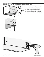
Страница 16: ...s hole for the line set drain line display cable and power wires 7 Raise the evaporator to the installation location Align the rear keyholes with the mounting screws and mount the unit 8 Using a wrench or socket tighten the top mounting screws 9 Using and 3 8 copper tubing route the liquid and suction lines through the knockouts in the housing Be sure to extend the tubing far enough outside of the...

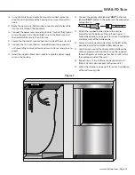
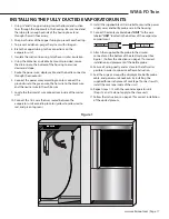
Страница 17: ...ack strain relief to secure the power supply wires in the housing 20 Connect the display cable labeled UNIT to the wire labeled UNIT located in the bottom of the evaporator compartment 46375 Figure 1 21 Attach the supplied bottle probe to the circular connector on the bottom of the unit see Figure 1 Follow the directions on page 21 for correct installation and placement of the bottle probe 22 Secu...

Страница 18: ...ne set power wires and drain line 2 Remove the insulation from the knockout holes 3 For ease of installation remove the nine 9 screws securing the top and remove the top 4 Follow the directions on page 22 to mount the remote display and run the display cable to the evaporator unit Power Line set Drain line Bottle probe connector routing location ...

Страница 19: ...re connections inside of the master unit 10 Connect the 18 5 wire that was routed between the evaporator units according to color yellow to yellow red to red and green to green 11 Install the supplied black strain relief to secure the power supply wires and bottle probe wire in the housing 12 Connect the display cable labeled UNIT to the wire labeled UNIT located in the bottom of the evaporator co...

Страница 20: ... 90 bends use a 90 adjustable elbow No more than two 90 bends on each duct Sweep 90 bends are recommended rather than sharp 90 bends NOTE For every 90 bend the system loses 13 CFM of airflow NOTE A 12 x 12 return air filter grille must be installed to prevent contaminants from entering the cooling system Supply duct must be insulated so it does not sweat or pick up heat Generously apply duct seala...

Страница 21: ...e pan for this application DUCTING CONFIGURATIONS There are several ways to duct this unit Please review the different configurations to determine a basis for your particular installa tion Remember to contact a wine cellar professional if you have any questions Indoor Installation Cold Air Supply Return Air Line Set to Condensing Unit MECHANICAL ROOM Condensing Unit Evaporator 1 Evaporator 2 ...

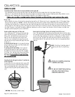
Страница 22: ... drain line connection tee and two 90 fittings Each unit is equipped with a 1 2 OD barbed fitting coming from the drip tray NOTE 1 2 ID clear PVC tubing will need to be purchased and installed by the installing technician Installation of the drain line is mandatory whether it leads through the wall and out of the cellar or remains inside the cellar During operation the cooling system will strip ex...

Страница 23: ... with room temperature tap water 3 Place bottle probe securely into bottle as seen in Figure 1 4 Place the wine bottle in your wine cellar Ensure sensor tip is fully submerged 5 To ensure a consistent temperature place bottle probe approximately three 3 feet away from the air output and not in the flow of the air It is recommended that the bottle be placed in a central location of your wine cellar...

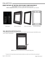
Страница 24: ...ALLATION AND CONFIGURATION NOTE Cut hole in the location shown for routing the display cable Tools needed 5 16 drill bit 3 16 drill bit drywall saw level pencil What s included Display panel wall mount bracket flush mount bracket flush mount template 55 F Display panel Wall mount bracket Flush mount bracket TOP Flush mount template The display can be mounted on any wall inside or outside the wine ...

Страница 25: ...ided drywall anchors into the drywall then tap them in with a hammer until they are flush with the wall WALL MOUNT BRACKET INSTALLATION CONTINUED 3 Place bracket against wall aligning screw holes with drywall anchors Insert the four supplied Phillips head screws into the drywall anchors Tighten the screws to secure the bracket to the wall ...

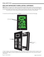
Страница 26: ...ct the end of the display cable labeled DISPLAY to the JST connector on the back of the display DIS PL AY JST connector NOTE Before you continue to Step 4 locate the area where the display will be mounted You may route the display wire into the housing one of three ways either through the wall or through one of the holes on the top or bottom edges of the wall mount bracket If you d like to route t...

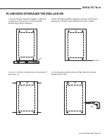
Страница 27: ...r of each cross 4 Cut along the perforated lines When finished remove template from wall INSTALLING THE EVAPORATOR 1 Locate the desired installation location 2 Place the external drip tray on a level surface Place a vibration isolator on each end of three of the drip tray risers The vibration isolator needs to be pushed up against the outer lip on the top of the risers Each vibration isolator shou...

Страница 28: ...TION CONTINUED 5 Remove the backing from the double sided tape on the flush mount bracket 6 Align magnets with previously drilled holes Make sure the cut out portion of the bracket circled below is on the bottom Press the bracket firmly against the wall WALL HOLE CUTOUT ...

Страница 29: ...y panel BRACKET DISPLAY 8 Place the display on the flush mount bracket as shown attaching the back of the display panel to the magnets on the mounting bracket Make sure that the alignment tab on the back of the display panel sits in the notch on the bot tom of the bracket FLUSH MOUNT BRACKET INSTALLATION CONTINUED WALL ...

Страница 30: ...er BLACK WHITE WHITE YELLOW 1 4 LINE SOLENOID Solenoid Relay 1 0 4 6 Fan Relay 1 0 4 6 BLACK BLACK BLUE BLUE BLUE BLACK 1 4 BLACK GREEN BLACK WHITE BLACK BLUE Ref Solenoid GREEN GREEN Evaporator Fan 1 4 1 4 GREEN BLUE GREEN YELLOW BLACK WHITE Field Installed LEGEND Factory Installed WHITE WHITE WHITE 115V LINE 115V NEUTRAL GROUND BLUE BLUE YELLOW GREEN MASTER UNIT SLAVE UNIT THE BOLD BLACK LINES B...

Страница 31: ...EN WHITE BLACK WHITE BLACK BLUE WHITE 4 Ref Solenoid GREEN GREEN FV 30VQ3 1 4 1 4 WHITE 115V LINE 115V NEUTRAL GROUND BLACK WHITE 1 1 4 RED 24v Transformer BLACK WHITE WHITE YELLOW BLUE BLUE YELLOW GREEN PS WM FD MASTER UNIT WIRING DIAGRAM YELLOW GREEN BLUE 24V 18 5 THERMOSTAT WIRES GOING TO SLAVE UNIT ...

Страница 32: ... BLUE BLUE BLUE BLACK 1 4 BLACK GREEN BLACK WHITE BLACK BLUE Ref Solenoid GREEN GREEN Evaporator Fan 1 4 1 4 GREEN BLUE GREEN YELLOW BLACK WHITE Field Installed LEGEND Factory Installed WHITE WHITE WHITE 115V LINE 115V NEUTRAL GROUND PS WM FD TWIN SLAVE UNIT WIRING DIAGRAM STANDARD AND 24V TCK BLUE GREEN YELLOW 24V 18 5 THERMOSTAT WIRES COMING FROM MASTER UNIT ...

Страница 33: ...www cellarcool com Page 31 WM FD Twin WM FD 9000 TWIN S CONDENSING UNIT WIRING DIAGRAM ...

Страница 34: ...Page 32 1 800 343 9463 WM FD TWIN 051019 COPELAND COLD WEATHER START KIT WIRING DIAGRAM L1 L2 HEATER TS Black Black 1 2 3 4 5 1 2 3 4 5 COPELAND 9 000 CWSK ...

Страница 35: ...erior applications will require the use of a protective housing The amount of sun exposure should be considered when selecting the placement of the condensing unit The condensing unit requires a dedicated 15 amp circuit non GFI Make sure there is a minimum of three 3 feet of horizontal clearance in every direction around the unit five feet is ideal The unit may either be hard wired or plug in depe...

Страница 36: ...ing according to this chart Platinum Split Twin Line Set Length 25ft 26 50ft 50 100ft Vertical Rise 15ft 3ft 3 10ft 10ft 3ft 3 10ft 10ft Suction Line Sizing 3 4 7 8 Liquid Line Sizing 3 8 3 8 Condensing Unit Installed Below Fan Coil Option 1 Condensing Unit Installed More Than 3 Above Fan Coil Option 2 EXAMPLE ...

Страница 37: ...ier to the tubing Downstream from the drier connect the moisture indicating sight glass in an easily visible location Run the tubing to the evaporator units and attach to the liquid line connection on the evaporator units Suction Piping Procedure Install an access valve at the outlet of the evaporator units Connect an appropriately sized suction line to the suction line service valve on the conden...

Страница 38: ...uit breaker for the condensing unit The compressor should turn on if the pressure in the suction line is above 25 psig Add refrigerant through the suction line service valve by throttling in small amounts of liquid refrigerant in two second intervals Refrigerant must be throttled in or the compressor may be damaged Observe the sight glass If bubbles are present add more refrigerant until the sight...

Страница 39: ...ALLING THE DUCTED PLENUM 1 If removed reinstall the top panel of the unit housing 2 Align duct plenum with the four 4 ball studs on the housing Push the duct plenum onto the ball studs until it snaps into place 3 Using a Phillips head screwdriver fasten the bottom two 2 screws to fasten the plenum to the unit 4 Connect the supply and return duct work to the unit 5 Using duct tape or foil tape seal...

Страница 40: ...D TWIN 051019 COPELAND WIRING PROCEDURE Copeland Wiring Procedure Step 1 Use a nut driver to remove the screws securing the cover to the compressor electrical compartment Copeland Wiring Procedure Step 2 Remove the cover as shown ...

Страница 41: ...peland Wiring Procedure Step 4 Route the required 208 230V power wires into the open clamp on the enclosure Copeland Wiring Procedure Step 3 Pull the controller panel forward and rest it in the down position to expose the internal compartment ...

Страница 42: ... Procedure Step 6 Connect Line 1 wire to the L1 lever connector Connect Line 2 wire to the L2 lever connector Connect ground wire to G lever connector Copeland Wiring Procedure Step 5 Tighten the screws on the clamp to secure wire casing or conduit in place ...

Страница 43: ...www cellarcool com Page 41 WM FD Twin Copeland Wiring Procedure Step 8 Re install cover Copeland Wiring Procedure Step 7 Push wires back into enclosure and place the controller panel back in place ...

Страница 44: ...roller is waiting for the Anti Short Cycle delay Anti Frost Cycle When the evaporator probe senses a temperature of 26 F for a duration of one minute an Anti Frost Cycle will be initiated This will shut down the compressor allowing the evaporator fan to run and melt any frost accumulation on the coil While the Anti Frost Cycle is running dEF will be displayed on the screen The compressor will rema...

Страница 45: ...n Fan is on Anti Frost Cycle running Alarm is present F F View Change Setpoint Enter User Menu hold for 3 sec Unlock Button hold for 1 sec Scroll Button Change Setpoint 55 F Power On Off Scroll Button Change Setpoint Return to Previous Menu DISPLAY LAYOUT ...

Страница 46: ...used to navigate through menus and adjust parameters such as setpoint Fon FOF etc SET To change the setpoint press the SET button When SEt is displayed on the screen press the SET button once more Use the UP and DOWN ARROW buttons in order to change the value until the desired setpoint is reached The SET button allows you to view the setpoint evaporator temperature bottle tempera ture alarms and t...

Страница 47: ...PPING SNOWFLAKE The unit is undergoing an Anti Frost Cycle While the Anti Frost Cycle is running dEF will be displayed on the screen See System Operation page for further details FAN The evaporator fan is running ALARM The alarm icon is shown when the unit encounters an issue that needs attention Alarm codes are explained on the following page All temperature related alarms are blocked for the fir...

Страница 48: ...e operation of your cooling unit The following alarm codes will not be displayed on the home screen However the alarm icon will be displayed in the event of an alarm The alarms can be viewed in the Set Menu s ALr folder EA Unit is not draining properly 1 Check to see that the unit is level if not level it 2 Verify that the drain line is not clogged if so clear obstruction 3 Ensure that the condens...

Страница 49: ...cellar s relative humidity you can adjust this setting in the User Menu Fon fan on The fan on time is preset to zero minutes This keeps the relative humidity of the wine cellar at a stable level If however you wish to raise the relative humidity of your wine cellar you can increase the duration of the fan on cycle in increments of five 5 10 or 15 minutes After making any adjustment to the fan on c...

Страница 50: ...ion StH CompressorStarts 1000 999999 StL Compressor Starts 0 999 CHH CompressorHours 1000 999999 CHL Compressor Hours 0 999 F1H Fan 1 Hours 1000 999999 F1L Fan 1 Hours 0 999 F2H Fan 2 Hours 1000 999999 F2L Fand 2 Hours 0 999 Example If StH 12 and StL 500 the total num ber of compressor starts 12 500 Adjusting Low Pressure Settings Hold DOWN and SET simultaneously for 3 seconds to enter menu PSI li...

Страница 51: ...sor resistance values against table in AE 1376 Section 8 Controller ashes P3 on a unit without DLT after replacing a controller Controller not programmed properly check parameters in the advanced menu Fans not running on a fan cycling unit and the fan lights are not on Condensing temperature is currently below the fan cut in Condensing temperature sensor not properly installed check installation T...

Страница 52: ...point Thermostat not calling for cooling Lower setpoint Faulty thermostat or wiring Call Customer Service at 1 800 343 9463 Cellar temperature is too warm Possible cause Solution The temperature of the room to which the condensing unit exhausts exceeds 110 F Intake temperature needs to drop below 110 F The system is undersized for the cellar Order correctly sized system There is something blocking...

Страница 53: ... control the system is going through an Anti Frost Cycle No action is required 2 If the system is not maintaining the correct cellar temperature this may be due to dirty evaporator filters or coils 3 Call installing technician to troubleshoot as the system may be low on charge or require an adjustment to the TXV Compressor and or starting components faulty Please contact the installing technician ...

Страница 54: ...they are above the waterline if draining into a vessel Quarterly 1 Use a vacuum with brush attachment to clean coils be careful not to crush coil fins when cleaning 2 Change duct filters if the system is ducted Annually 1 Inspect for corrosion 2 Check wiring connections and integrity of cords 3 Pour a 50 50 bleach solution into the drain lines every spring ...

Страница 55: ...ents introduced into the condensate pan can accelerate pan and or tube corrosion As foreign agents are introduced into the condensate pan condensatewaterwillbeevaporatedleavingtheforeign agentbehind Thiscanleadtoahighconcentrationofthe agent and possible corrosion of the tubing and or base Coil cleaning agents must not be allowed to drain into the condensate pan as this may cause damage Upon compl...

Страница 56: ... two 2 hooks which allow it to attach to the evaporator units for easy serviceability 6 Disconnect the Molex connector labeled 4 7 Locate the bypass plug included in the accessory kit 8 Plug the bypass plug into the male Molex connector 9 Connect power to the evaporator units The system should immediately turn on If all the components are not operational disconnect power immediately and contact cu...

Страница 57: ...ool com ACCESSORIES FOR COOLING UNITS CellarCool Customer Service is available Monday through Friday from 6 00 a m to 4 00 p m Pacific Standard Time The appointed customer service representative will be able to assist you with your questions and warranty information more effectively if you provide them with the following The model and serial number of your CellarCool system s Location of unit and ...

Страница 58: ...lit Startup Checklist is approved Purchaser will be sent activation approval documents and will start receiving the benefits of the Limited Warranty throughout the warranty period If the Split Startup Checklist is incomplete Purchaser will be informed they have five days to complete the Split Startup Checklist and re submit to CellarCool The Split Startup Checklist will be reviewed again and if de...

Страница 59: ...of of purchase of the Product in the form of a bill of sale receipted invoice or serial number which is evidence that the Product is within the Limited Warranty Period must be presented by the End User to CellarCool in order to obtain limited warranty service 7 This limited warranty is void if the factory applied serial number has been altered or removed from the Product 8 This limited warranty is...

Страница 60: ... Product is found to be irreparable in the field contact CellarCool Customer Service to arrange for replacement under the warranty guidelines When a claim for warranty is submitted for a condenser skid the End User must purchase a new condenser skid from CellarCool at retail price Upon installation of the new condenser skid by a certified HVAC R Technician the HVAC R Technician must complete the I...

Страница 61: ...ool will provide all documentation to the customer to substantiate the findings This will include the Invoice from the Independent Certified HVAC R Technician and the written report of the findings The Owner will become responsible for payment directly to CellarCool for all charges incurred for repairs labor parts and shipping costs on the Split System 8 Miscellaneous Terms and Conditions A Return...

Страница 62: ...hnical Assistance CellarCool Customer Service is available Monday through Friday from 6 30 a m to 4 00 p m PST The Customer Service representative will be able to assist you with your questions and warranty information more effectively if you provide them with the following 1 The model and serial number of your CellarCool UNIT 2 The location of the system and installation details such as ventilati...

Страница 63: ...CellarCool 1738 E Alpine Ave Stockton CA 95205 1 800 343 9463 www cellarcool com ...

Отзывы: